
Combination steamer

Inactive Publication Date: 2010-03-04
MAIER MAX
View PDF3 Cites 20 Cited by
  • Summary
  • Abstract
  • Description
  • Claims
  • Application Information

AI Technical Summary

Benefits of technology

[0006]It is an object of the present invention to overcome the drawbacks of the prior art described above and to substantially expand the field of application of the combination steamer.

Problems solved by technology

However, this does not rule out the possibility of providing a fan outside the cooking chamber and allowing its pressure side to communicate with the cooking chamber.

Method used


Image

  • Combination steamer
  • Combination steamer
  • Combination steamer

Examples


first embodiment

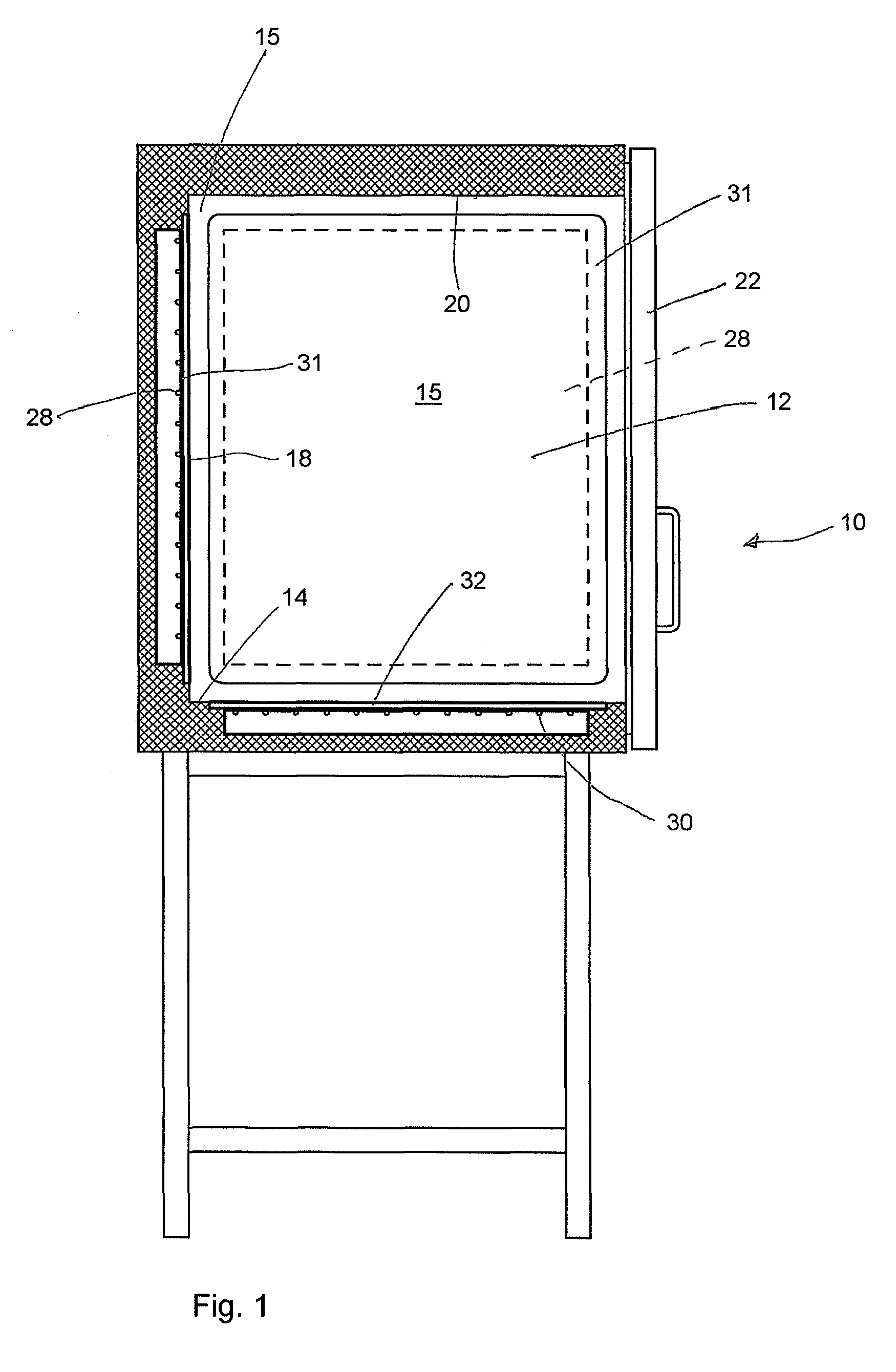
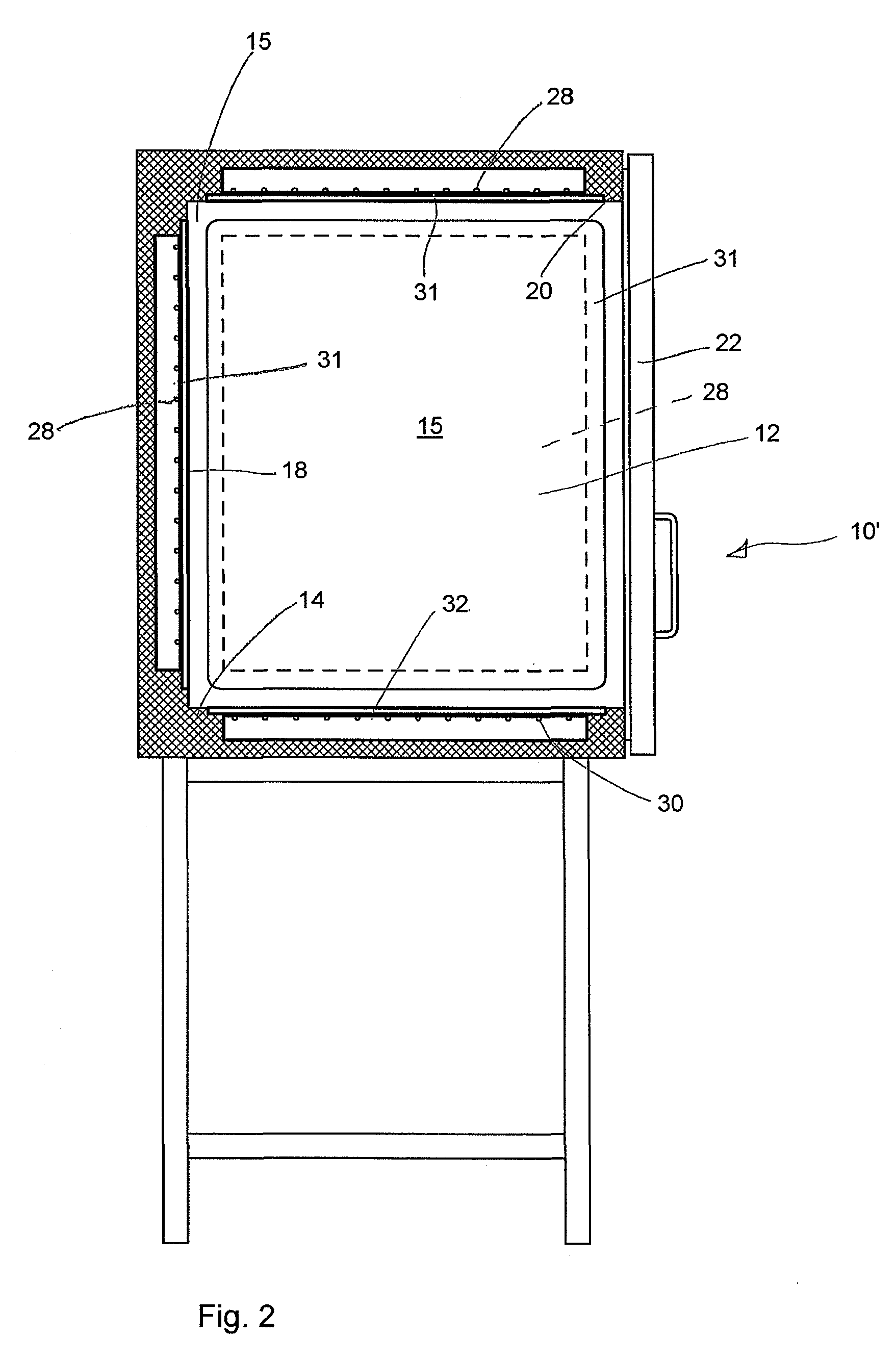
[0030]The two opposing side walls 15 and 16 and the rear wall 18 (as mentioned above, the side wall 16 is not visible in FIG. 1 and is shown in FIG. 4) in the combination steamer 10 have the same architecture as the floor 14 and are each formed as heating panels 31 provided with a first heater 28. A fourth side wall is not present but is instead formed by an opening offering access to the cooking chamber 12, which opening can be closed by means of the door 22. Unlike the prior art described above, the side walls 15, 16, and the rear wall 18 are also continuous walls, and the first heater is disposed behind these walls, that is to say, outside the cooking chamber 12. Each of the heating panels 31 is composed of a plate made of glass-ceramics or the like or of a metallic multilayered material and is embedded in the wall and performs the function of delimiting the cooking chamber laterally whilst making it possible to heat the cooking chamber without any need for the first heater to be...

third embodiment

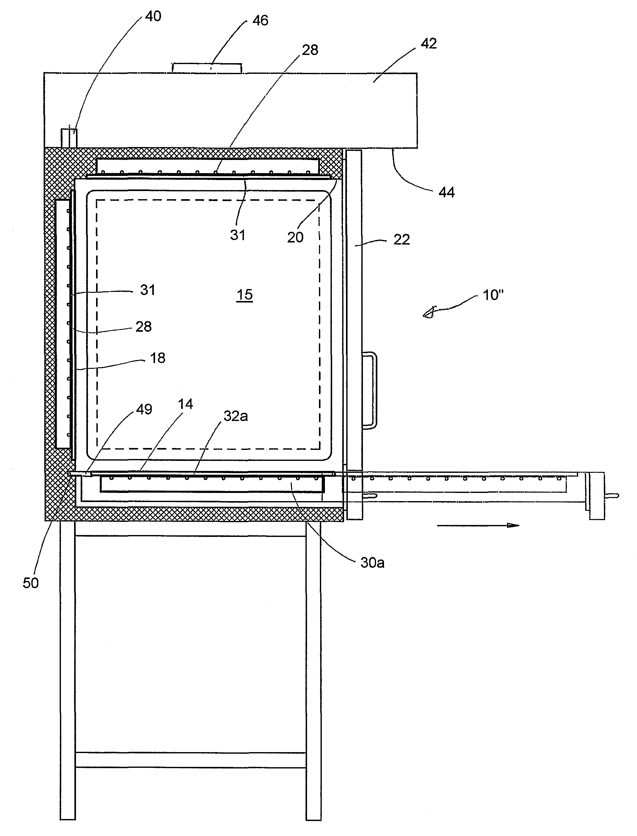
[0034]FIG. 3 shows a combination steamer designated as a whole by reference numeral 10″ as the invention. In the combination steamer 10″, the cook top 32 is designed as one that can be retracted from the cooking chamber 12 in the manner of a drawer, as shown in FIG. 3. FIG. 4 is a front view of the combination steamer 10″, with the door 22 of the cooking chamber 12 not shown for the sake of clarity. In combination steamer 10″ also, the cook top 32 forms the floor and thus forms the bottom delimitation of the cooking chamber 12. The ability of the cook top 32 to be retracted to a position shown in FIG. 3 makes it easier for the user of the combination steamer 10″ to work when the cook top 32 is used as a stove. As in the case of the first two embodiments, the cook top 32 can comprise a plurality of hot plates and the second heater 30 can comprise a plurality of heating means assigned individually to each of the hot plates. In the exemplary embodiment shown in FIGS. 3 and 4, the secon...


PUM


Abstract

A combination steamer is described that has a cooking chamber which is externally delimited by a floor, walls, and a door. A steam generator and a first heater disposed on at least one of the walls are assigned to the cooking chamber. The floor is provided with a second heater. Both heaters are disposed outside the cooking chamber. The floor is formed as a cook top provided with the second heater. The walls are each in the form of a heating panel provided with a first heater. The cook top is retractable from the cooking chamber in the manner of a drawer. Thus food can be cooked on the cook top when the cook top is either inside or outside the cooking chamber.

Description

BACKGROUND OF THE INVENTION[0001]1. Field of the Invention[0002]The invention relates to a combination steamer comprising a cooking chamber externally delimited by a floor, walls, and a front door, and having a steam generator, and a first heater disposed on at least one of the walls and a second heater disposed on the floor.[0003]2. Description of Related Art[0004]A known combination steamer of this type (DE 201 05 820 U1) is designed for cooking by means of hot air and / or steam. In general, combination steamers are a combination of a steam cooker and an oven. They are used either for baking or for steam cooking. Food to be cooked can be simply steamed while at, say, 100° C. water is repeatedly injected. In the known combination steamer, this injected water is vaporized by the first heater. The first heater, which is mounted on the inside surface of a wall of the cooking chamber, comprises a fan adapted to circulate the generated steam in the cooking chamber. Since, in general, dir...

Claims


Application Information

Patent Timeline
IPC IPC(8): A47J27/16
CPCF24C7/06F24C15/327F24C15/30
Inventor MAIER, MAX
Owner MAIER MAX
Learn More