RFID tag with external binding area

An RFID tag and binding area technology, applied in the field of RFID tags, can solve the problems of increasing the complexity of the production process, occupying the internal size of the antenna, increasing the cost of the antenna, etc., to reduce the complexity and production cost, reduce the number of bridges, design handy effect

Pending Publication Date: 2020-05-12
SHANGYANG RFID TECH YANGZHOU
View PDF0 Cites 0 Cited by
  • Summary
  • Abstract
  • Description
  • Claims
  • Application Information

AI Technical Summary

Problems solved by technology

Conventional tags are all RFID high-frequency tags with the binding area located inside the label, multi-coil winding and bridge design. Since the binding area of ​​this type of RFID high-frequency tag is located in the middle of the chip, the binding area needs to be reserved and more designs are required. bridges (4 bridges are required for the internal design of the bonding area); this design method will occupy the internal size of the antenna, and multiple bridges will increase the cost of the antenna, and the proximity of multiple bridges to the bonding area will make the antenna bonded in production Timing produces uneven hot pressing, which increases the complexity of the production process

Method used


Image

  • RFID tag with external binding area
  • RFID tag with external binding area
  • RFID tag with external binding area

Examples


Embodiment Construction

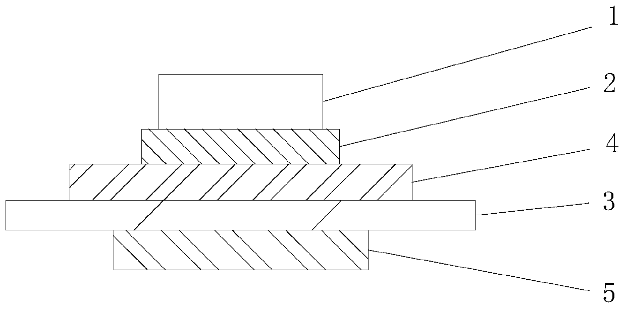
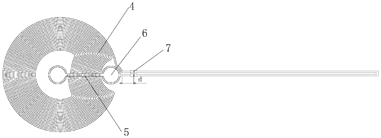
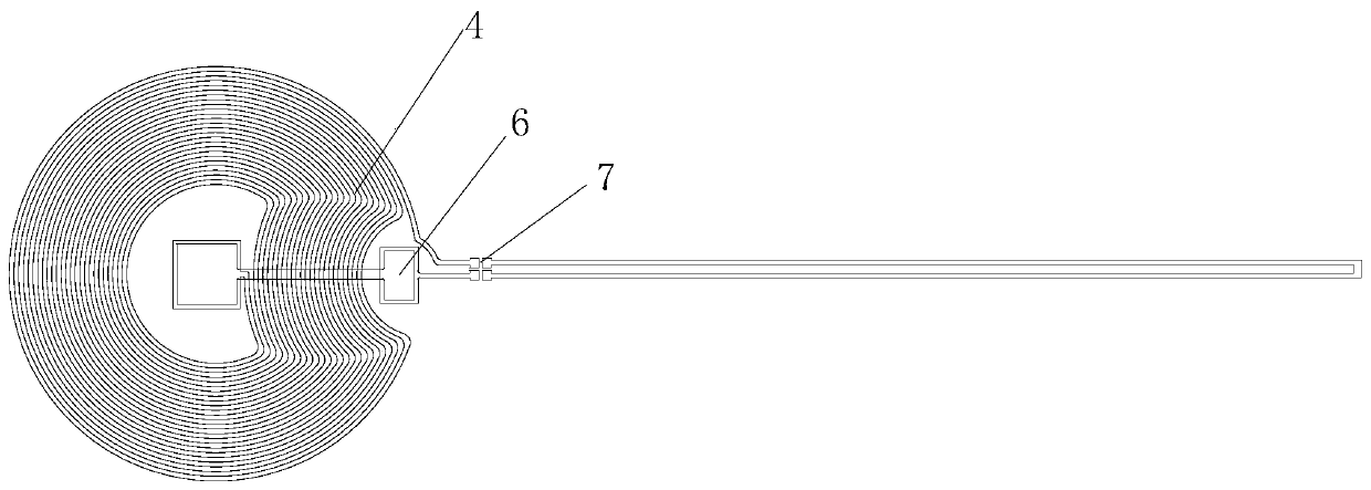
[0022] The present invention as Figure 1-4 As shown, it includes a tag antenna and a chip 1. The tag antenna includes a substrate 3, a front metal antenna 4, a back metal antenna 5 and two bridges 6. The front metal antenna is arranged on the front of the substrate and includes a metal coil. The back metal antenna is arranged on the back of the substrate and includes an inline transmission line, one end of the transmission line is connected to the inside of the metal coil through a bridge, and the other end is connected to the outside of the metal coil through another bridge;

[0023] The binding area of ​​the chip (area for binding the chip) is set outside the tag antenna. The chip is connected to the front metal antenna through conductive glue 2.

[0024] The design of the binding area adjustment, the high-frequency antenna binding area is adjusted from the original internal position to the external position of the tag antenna, and can be adjusted to any position outside t...


PUM


Abstract

The invention discloses an RFID tag with an external binding area. The invention relates to the technical field of RFID tags, in particular to an RFID tag with an external binding area. The RFID tag with the external binding area is space-saving, convenient to process and low in cost and comprises a tag antenna and a chip, wherein the tag antenna comprises a base material, a front metal antenna, aback metal antenna and two gap bridges; the front metal antenna is arranged on the front surface of the base material and comprises a metal coil; the back metal antenna is arranged on the back surface of the base material and comprises a linear transmission line; one end of the transmission line is connected to the interior of the metal coil through a gap bridge; and the other end of the transmission line is connected to the exterior of the metal coil through the other gap bridge; and the binding area of the chip is arranged on the outer side of the tag antenna. The antenna appearance and thegap bridge appearance can be flexibly adjusted and designed, so that the earlier-stage design is more convenient, and the use scene is wider.

Description

technical field [0001] The invention relates to the technical field of RFID tags, in particular to an RFID tag outside a binding area. Background technique [0002] Radio Frequency Identification (RFID) technology, also known as radio frequency identification, is a communication technology that can identify specific targets through radio signals and read and write related data without establishing mechanical or optical contact between the identification system and specific targets. [0003] With the promotion and application of RFID technology in various fields, for different application environments, the functions and requirements of electronic tags are getting higher and higher, and the intelligence of tags is gradually improved. Such as Figure 5 As shown, the existing high-frequency tag consists of a back metal antenna (i.e. back metal antenna 1 81 and back metal antenna 2 82), a base material, a front metal antenna 4, a conductive glue 2 and a chip 1, and the back metal...

Claims


Application Information

Patent Timeline
Patent Type & Authority Applications(China)
IPC IPC(8): G06K19/077H01Q1/22
CPCG06K19/0772G06K19/07773H01Q1/2216
Inventor 孙升琦邓元明伯林林超徐新宇
Owner SHANGYANG RFID TECH YANGZHOU
Why Eureka
Try Eureka