Electronic component

a technology of electronic components and components, applied in the direction of transformers/inductance details, inductances, inductances with magnetic cores, etc., can solve the problems of easy peeling of poor connection between internal electrodes and external electrodes. to achieve the effect of enhancing the connection between an internal electrode and an external electrod

Active Publication Date: 2010-03-04
MURATA MFG CO LTD
View PDF7 Cites 55 Cited by
  • Summary
  • Abstract
  • Description
  • Claims
  • Application Information

AI Technical Summary

Benefits of technology

[0011]The present invention has been made in consideration of the above-described problems in the related art. Accordingly, it is an object of t...

Problems solved by technology

As a result, there is a problem in that the internal electrode and the external electrode are peeled off thereby easily causing a poor connection.
However, the linear expansion coefficients of these materials for the substrate are small as compared with that of the resin and, therefore, poor connection between the internal electrode and the external electrode tends to occur easily along with temperature changes.
As a result, the thickness dimension of the exposed end surface of the internal electrode is on the order of several micrometers and, therefore...

Method used


Image

  • Electronic component
  • Electronic component
  • Electronic component

Examples


first embodiment

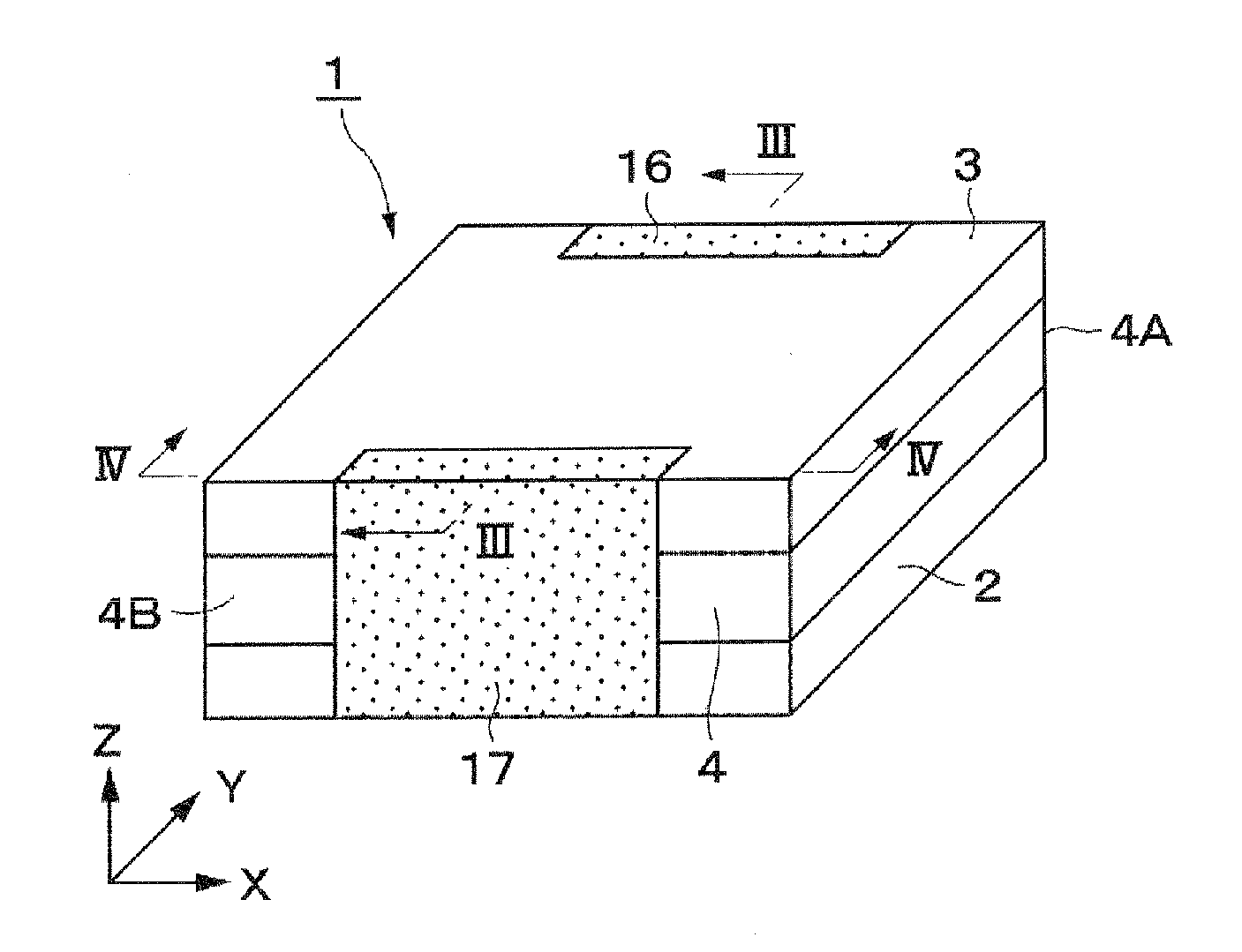
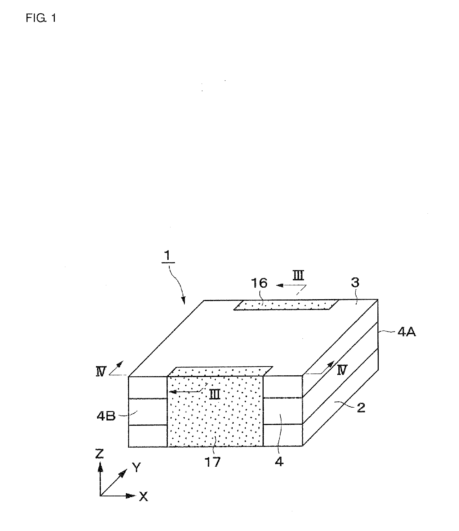
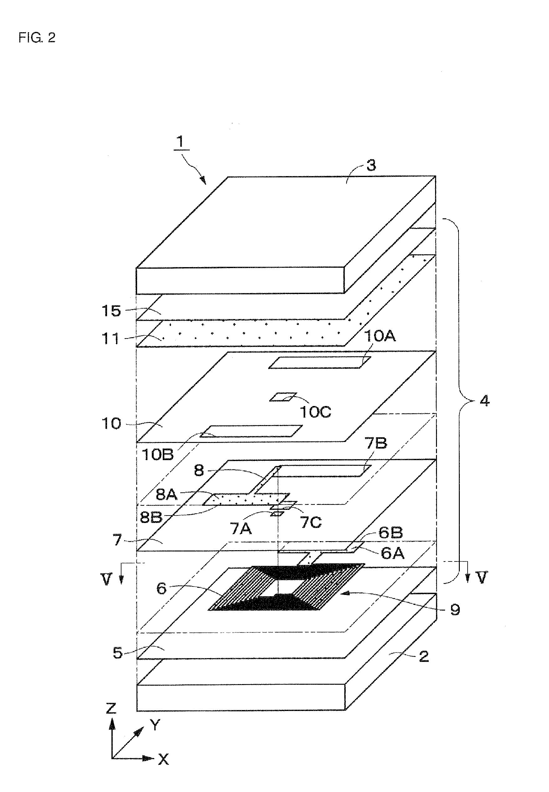
[0040]As summarized above, FIG. 1 to FIG. 5 show a first embodiment according to the present invention. A coil component 1 serving as an electronic component includes first and second magnetic substrates 2 and 3 serving as ceramic substrates and a laminate 4 sandwiched between the magnetic substrates 2 and 3. The magnetic substrates 2 and 3 are substantially formed into the shape of, for example, a quadrangle extending along an X-Y plane. In addition. The magnetic substrates 2 and 3 are formed by using a magnetic material, e.g., ferrite, serving as a ceramic material. In particular, in the case where ferrite is used for the magnetic substrates 2 and 3, the coil component 1 has a high inductance and excellent high-frequency characteristics.

[0041]The laminate 4 is formed by laminating resin insulating layers 5 and 10, a coil 9, and the like, which will be described later, in a thickness direction (i.e., Z direction).

[0042]A first resin insulating layer 5 is located on a surface of the...

second embodiment

[0083]FIG. 6 to FIG. 10 show a second embodiment according to the present invention. The present embodiment is characterized in that two substantially spiral coil patterns serving as the electrode patterns are disposed in the inside of a laminate, while being opposed to each other in the thickness direction to constitute a common mode choke coil circuit serving as an internal circuit.

[0084]Incidentally, in the present embodiment, the same constituents as those in the above-described first embodiment are indicated by the same reference numerals as those set forth above and further explanations thereof will not be provided.

[0085]A common mode choke coil component 21 includes first and second magnetic substrates 2 and 3 and a laminate 22 sandwiched between the magnetic substrates 2 and 3. The laminate 22 is formed by laminating resin insulating layers 23, 28, and 33, coils 27 and 32, and the like, which will be described later, in a thickness direction.

[0086]A first resin insulating la...


PUM


Abstract

An electronic component is configured to include a laminate disposed between first and second magnetic substrates. The laminate is formed by laminating resin insulating layers, a coil pattern, and a lead pattern. The coil pattern is connected to external electrodes disposed on end surfaces of the laminate by using internal electrodes. The electronic component further includes expansion relaxation portions disposed in the inside of the resin insulating layers and located in the vicinity of connection regions of the internal electrodes and the external electrodes. The expansion relaxation portions are formed by using a magnetic powder resin in which a ferrite powder and a resin material are mixed.

Description

CROSS REFERENCE TO RELATED APPLICATIONS[0001]The present application claims priority to Japanese Patent Application No. 2008-223408, filed Sep. 1, 2008, the entire contents of each of the application being incorporated herein by reference in its entirety.BACKGROUND OF THE INVENTION[0002]1. Field of the Invention[0003]The present invention relates to an electronic component including a laminate formed from a plurality of resin insulating layers, wherein internal electrodes are connected to external electrodes on end surfaces of the laminate.[0004]2. Description of the Related Art[0005]In general, an electronic component in which a laminate is formed by laminating, for example, resin insulating layers and a coil pattern and, in addition, the laminate is held between two magnetic substrates has been disclosed in the related art, for example, Japanese Unexamined Patent Application Publication No. 8-203737. In this case, internal electrodes connected to the coil pattern are exposed at en...

Claims


Application Information

Patent Timeline
IPC IPC(8): H01F5/00
CPCH01F17/0013H01F27/292H01F17/04
Inventor MATSUTA, KATSUJIKAWAGUCHI, MASAHIKO
Owner MURATA MFG CO LTD
Why Eureka
Try Eureka