Systems and Methods Employing Coupling Elements to Increase Antenna Isolation

a technology of coupling elements and antenna isolation, applied in the field of multi-element antennas, can solve the problems of affecting the amount of mutual coupling between antenna elements, affecting the performance of the antenna, and affecting the space between antenna elements in the system becoming more scarce, so as to achieve the effect of reducing production costs and saving spa

Inactive Publication Date: 2010-03-04
HONG KONG APPLIED SCI & TECH RES INST
View PDF14 Cites 92 Cited by
  • Summary
  • Abstract
  • Description
  • Claims
  • Application Information

AI Technical Summary

Benefits of technology

[0006]Various embodiments of the invention are directed to systems and methods that include a coupling element in a multiple-element antenna system. In one example, a coupling element is placed between two antenna elements. The shape of the coupling element is designed so that it cancels out the current that is due to direct coupling of the elements. In some embodiments, the coupling element can be quite small, thereby offering economy of space. Furthermore, various embodiments are much less complex than PBG-inspired designs and, thus, are cheaper to manufacture than prior art systems that use PBG-inspired isolation elements.

Problems solved by technology

As antenna systems grow smaller, space between antenna elements in those systems becomes more scarce.
Not only does the spacing between antenna elements have the potential to affect the radiation pattern of a system, but it can also affect the amount of mutual coupling between antenna elements.
Mutual coupling is inductive / capacitive coupling between two or more antennas, and it can sometimes result in unwanted performance degradation by interfering with signals being transmitted or by causing an antenna element to radiate unwanted signals.
In such systems, the antenna elements can induce currents in the ground plane that travel to other antenna elements and increase undesired coupling.
However, such systems generally produce an inadequate amount of isolation.
However, such systems are expensive in terms of both space and money because of the complexity of the three-dimensional shapes of the structures.
Currently, no prior art system provides adequate isolation with a minimum of complexity.

Method used


Image

  • Systems and Methods Employing Coupling Elements to Increase Antenna Isolation
  • Systems and Methods Employing Coupling Elements to Increase Antenna Isolation
  • Systems and Methods Employing Coupling Elements to Increase Antenna Isolation

Examples


Embodiment Construction

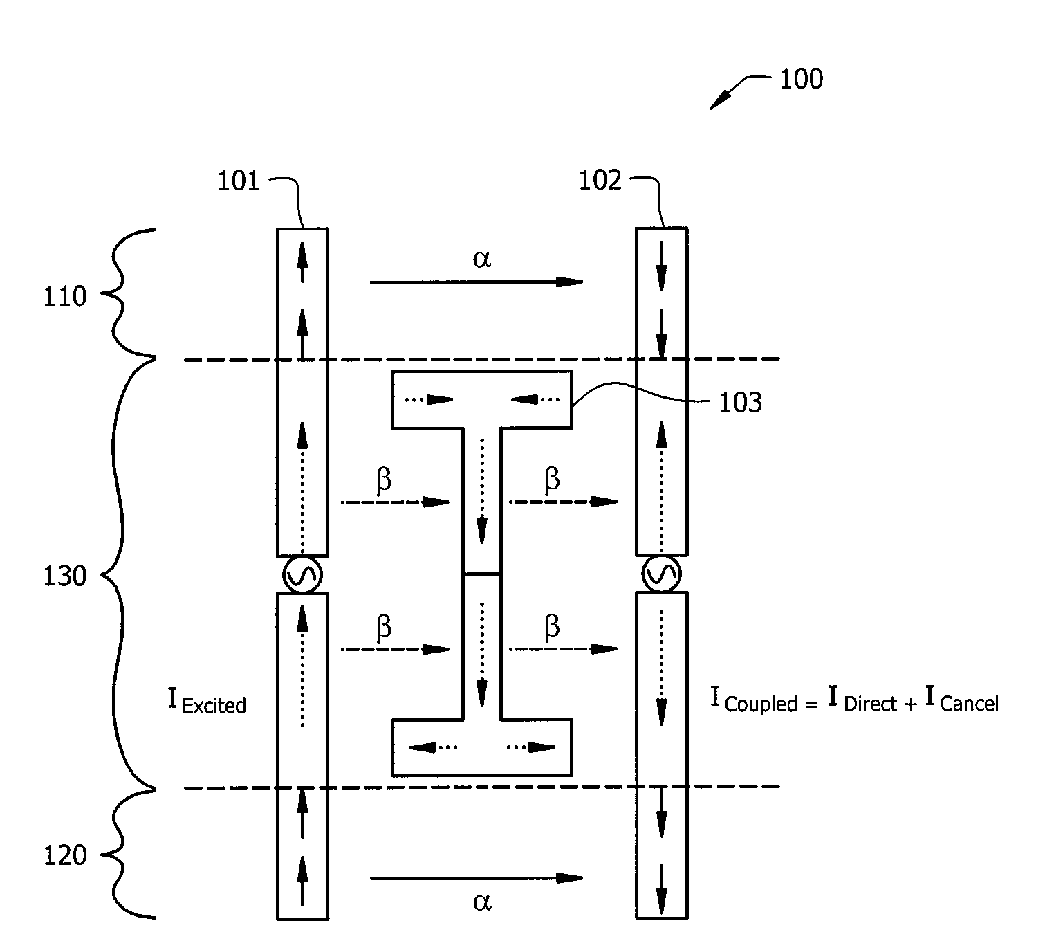
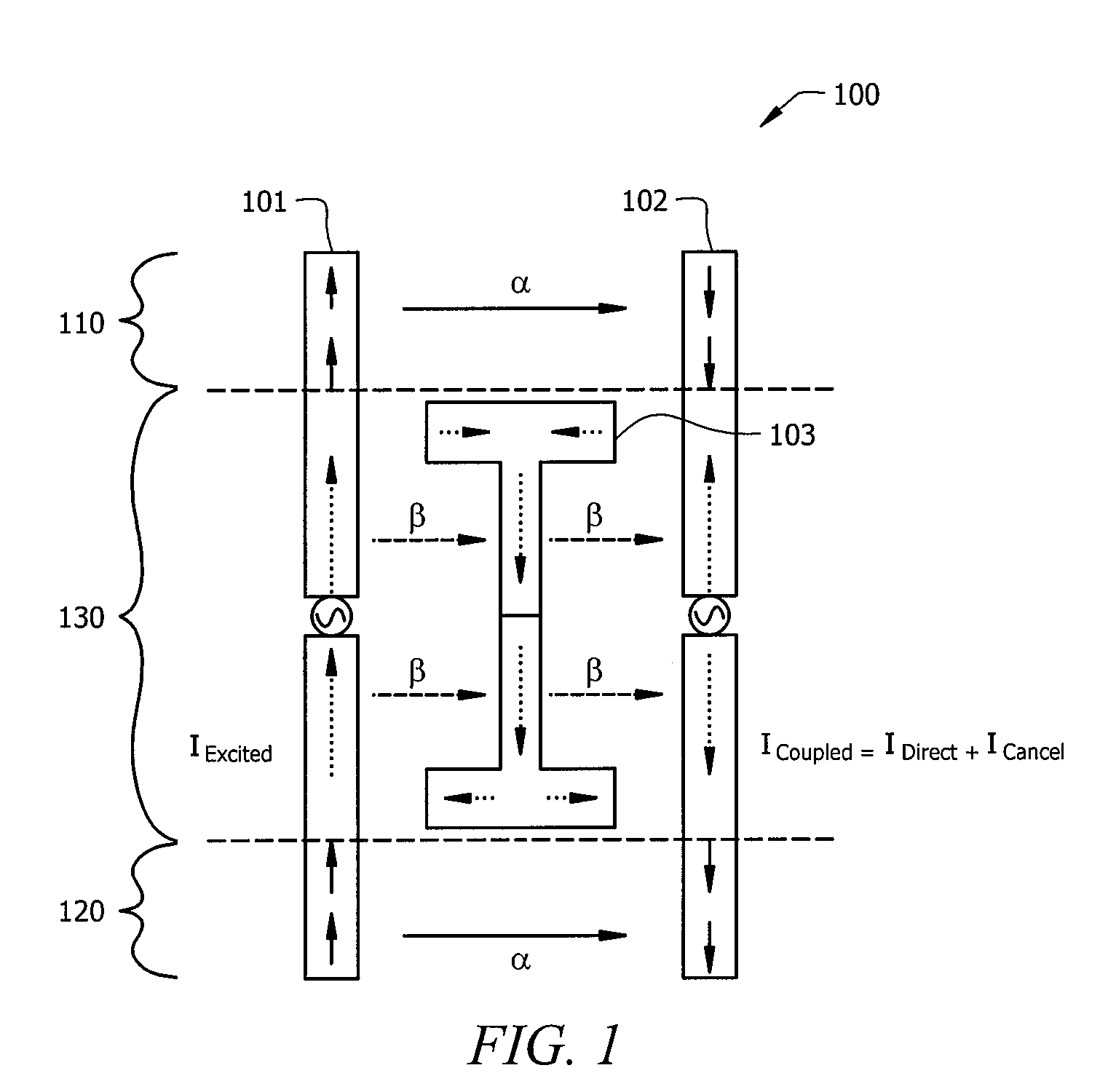
[0017]FIG. 1 is an illustration of exemplary antenna system 100, adapted according to one embodiment of the invention. System 100 includes antenna elements 101 and 102, as well as coupling element 103. In this example, antenna element 101 is driven by a Radio Frequency (RF) feed, and the current in antenna element 101 is IExcited. The total current in antenna element 102 that is due to mutual coupling with antenna element 101 is ICoupled.

[0018]There are three regions of interest in FIG. 1. Region 110 is where coupling element 103 does not lie between antenna elements 101 and 102. In other words, in region 110, each antenna element 101 and 102 is in the other's line of sight. Region 120 is similar to region 110. In region 130, coupling element 103 is positioned between antenna elements 101 and 102.

[0019]In regions 110 and 120, there is direct coupling between antenna elements 101 and 102. The current due to direct coupling is referred to in this example as IDirect, and it is equal to...


PUM


Abstract

An antenna system comprises a first antenna element mutually coupled with a second antenna element, the mutual coupling between the first and second antenna elements causing a first current in the second antenna element, and a coupling element disposed at least partially between the first and second antenna elements, wherein the coupling element is mutually coupled to each of the first and second antenna elements, and wherein the coupling element is configured to induce a second current in the second antenna element that at least partially cancels the first current.

Description

TECHNICAL FIELD[0001]The present description is directed, generally, to multiple-element antennas and, more specifically, to systems and methods employing components to reduce the effects of mutual coupling between and among multiple antenna elements.BACKGROUND[0002]As antenna systems grow smaller, space between antenna elements in those systems becomes more scarce. Not only does the spacing between antenna elements have the potential to affect the radiation pattern of a system, but it can also affect the amount of mutual coupling between antenna elements. Mutual coupling is inductive / capacitive coupling between two or more antennas, and it can sometimes result in unwanted performance degradation by interfering with signals being transmitted or by causing an antenna element to radiate unwanted signals. Generally, the closer the placement of two antenna elements, the higher the potential for mutual coupling.[0003]Accordingly, modern antenna designers generally look for ways to decrea...

Claims


Application Information

Patent Timeline
Patent Type & Authority Applications(United States)
IPC IPC(8): H01Q21/00
CPCH01Q1/2283H01Q9/0421H01Q1/523
Inventor MAK, ANGUS C. K.ROWELL, CORBETT R.MAK, CHI-LUN
Owner HONG KONG APPLIED SCI & TECH RES INST
Why Eureka
Try Eureka