Pump having electrolysis function

a technology of electrolysis and pump, which is applied in the direction of mechanical equipment, machines/engines, liquid fuel engines, etc., can solve the problems of requiring additional cost, requiring cost, and difficulty in installation of electrolysis devices, so as to reduce the cost, reduce the cost, and reduce the cost

Active Publication Date: 2019-07-23
WHA CHEON CO LTD
View PDF10 Cites 0 Cited by
  • Summary
  • Abstract
  • Description
  • Claims
  • Application Information

AI Technical Summary

Benefits of technology

[0012]According to the present invention, the electrode mounting hole is formed on the pump body of the pump, so that, if the electrode is mounted on the pump body, the supplied water introduced into the channel inside the pump body is electrolyzed. That is, as the pump itself has a function of electrolysis device, there is no need to install a separate electrolysis device on the pipe, which is economical and space saving in comparison with installing a separate electrolysis device.
[0013]Accordingly, only if the pump is operated, the fed material introduced into the pump, that is, the supplied water will be electrolyzed and sterilized, and the sludge in the pipe is also removed to achieve a cleaning effect of the pipe.
[0007]According to another aspect of the present invention, there is provided a pump having electrolysis function wherein, the pump body comprises a main body having the inlet on one side, the outlet on the other side, and a first opening formed adjacent to the outlet and facing to the side direction; and a back plate mounted on the first opening and on which the motor is attached, and the electrode mounting hole is formed on the back plate so that the electrode should be mounted on the back plate.
[0015]And, as the electrolysis chamber is formed in the pump, and the electrode is positioned in the electrolysis chamber, and if dilute HCl is used as electrolyte, hypochlorous acid is produced, so sterilizing effect of the water supplied in the pipe is enhanced, and cleaning effect on the pipe is also increased, and the scale formed on the electrode is also removed effectively. So there is no need to take measures to remove the scale on the electrode.
[0016]In addition, if the electrolysis chamber is integrated with the back plate which is a part of the pump body, the manufacturing or fabrication of the pump is easy than when separated electrolysis chamber is attached on the pump body, and the invention can be easily achieved by utilizing the conventional pump structure.

Problems solved by technology

For this, the separate electrolysis device should be installed on the water supply pipe, which requires an additional cost.
And, space is required to accommodate the electrolysis device, so if space is narrow, the electrolysis device is difficult to install.
Therefore, it is required to remove the scale on the electrodes periodically, which is troublesome.
And HCl is generally used to remove the scale from the electrodes, and it requires the cost.

Method used


Image

  • Pump having electrolysis function
  • Pump having electrolysis function
  • Pump having electrolysis function

Examples


first embodiment

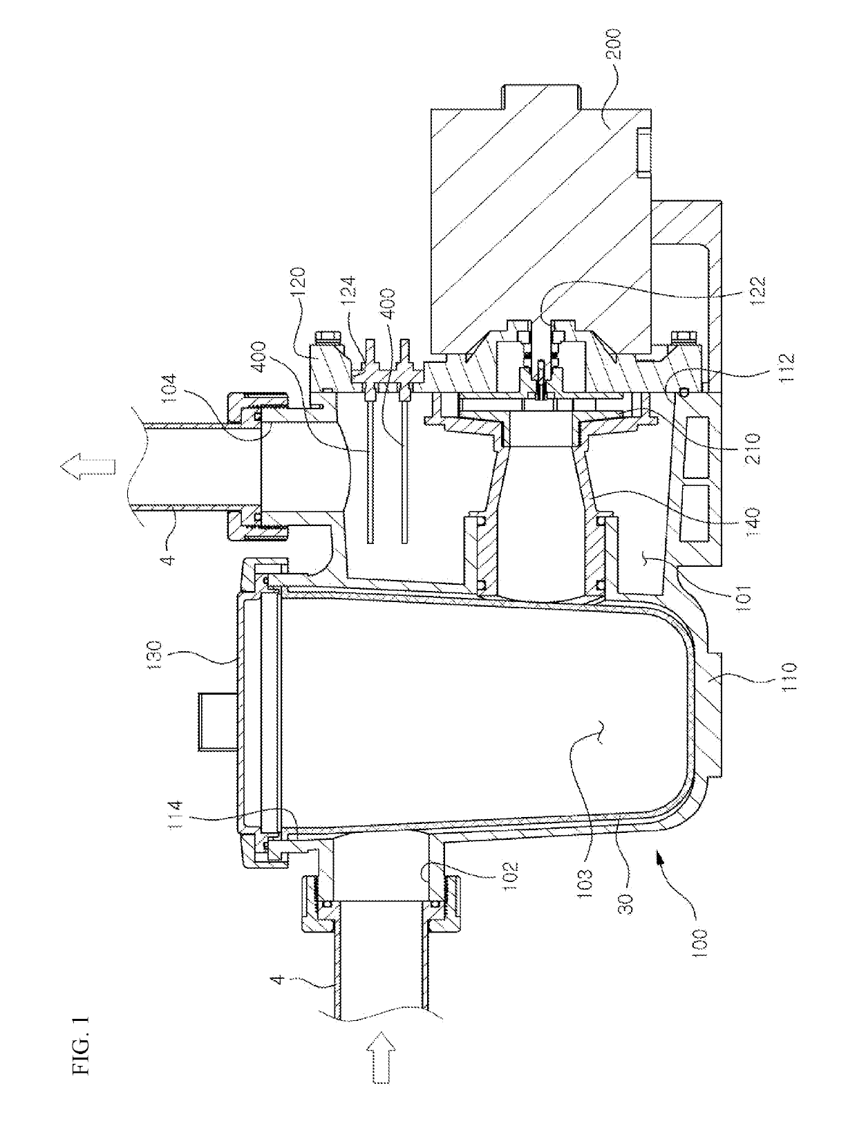
[0024]Hereinafter, the preferred embodiments of the invention will be described with reference to the drawings. FIG. 1 is a sectional view of the present invention. As shown, the invention includes a pump body 100 having a channel 101 formed therein, a motor 200 and electrodes 400. One end of the channel 101 in the pump body 100 is an inlet 102 and the other end of the channel 101 is an outlet 104, to which the pipe 4 is connected, so the pipe 4 is communicated with the channel 101 of the pump body 100. A part of the channel 101 is enlarged to form a filter section 103 to accommodate the filter 30.

[0025]As described above, the inlet 102 is formed at one end of the pump body 100 and the outlet 104 is formed at the other end of the pump body 100, and the pump body 100 comprises the main body 110 which has a first opening 112 preferably formed adjacently to the outlet 104 and a second opening 114 formed on the upper surface of it to accommodate the filter section 103, a back plate 120 ...

second embodiment

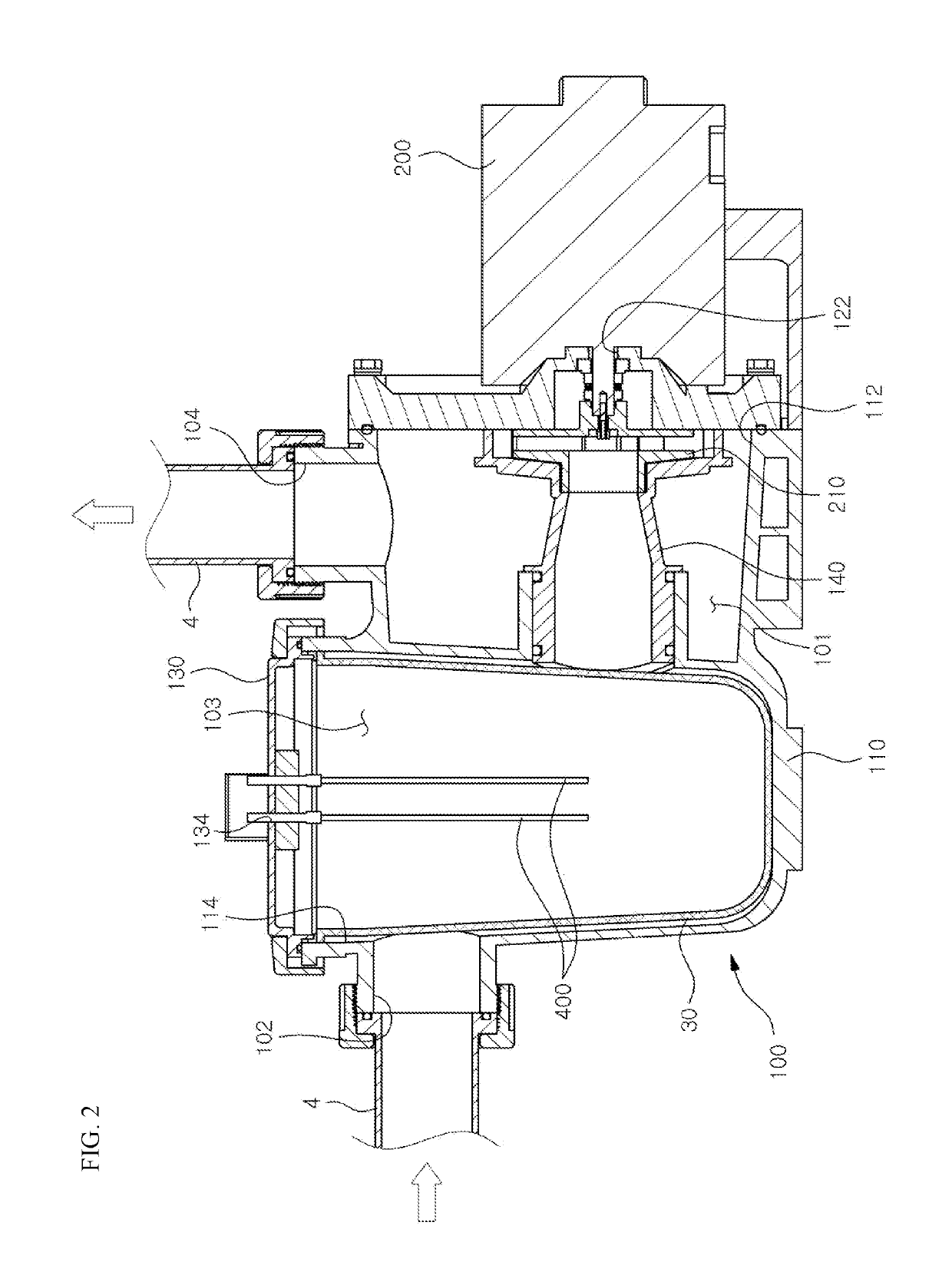
[0034]FIG. 2 shows the present invention, in which an electrode mounting hole 134 is formed on the filter cover 130, so that the electrode 400 is mounted on the filter cover 130.

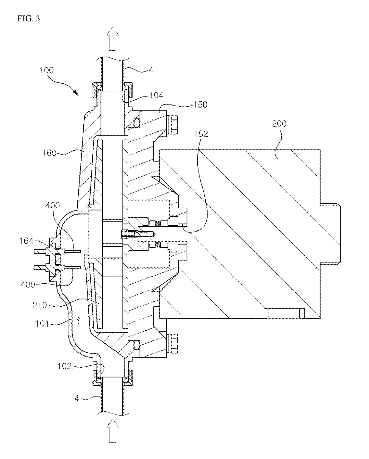
[0035]FIG. 3 shows the third embodiment of the present invention, in which the pump body 100 includes a back plate 150 on which the motor 200 is mounted and a impeller case 160 having an inlet 102 and an outlet 104 and being engaged with the back plate 150 to cover the impeller 210 of the motor. If the impeller case 160 is engaged with the back plate 150, the space between the back plate 150 and the impeller case 160 forms the channel 101. Numeral 152 is a shaft-hole formed on the back plate 150 to be penetrated by the shaft of the motor 200.

[0036]In this embodiment of the present invention, the electrode mounting hole 164 is formed on the impeller case 160, so that the electrode 400 is mounted on the impeller case 160. Preferably, the electrode 400 is formed as electrode unit, so that the electrode unit can...

fourth embodiment

[0037]FIG. 4 shows the present invention. According to the embodiment of the invention, an electrolysis chamber 300 is formed inside the pump, and the electrode 400 is positioned in the electrolysis chamber 300. As shown, the electrolysis chamber 300 has an electrolyte inlet 302 through which electrolyte is introduced and an electrolyte outlet 304 through which the electrolyzed material is discharged, and the electrolyte outlet 304 is communicated with the channel 101. The electrolysis chamber 300 is integrated with the back plate 120. The electrolyte inlet 130 is connected with the electrolyte supply line 2, and the preferable electrolyte is dilute HCl.

[0038]The electrode mounting hole 124 is formed on the back plate 120 to be communicated with the electrolysis chamber 300, so, if the electrode 400 is inserted in the electrode mounting hole 124, the electrode 400 may be positioned in the electrolysis chamber 400. As shown, the electrode 400 has a projection 410 at the front end pro...


PUM

PropertyMeasurementUnit
electric poweraaaaaaaaaa
suction forceaaaaaaaaaa
structureaaaaaaaaaa

Abstract

A feed water pump includes an electrolytic bath and is configured to have a high space-utilization and economical since a separate electrolysis device does not have to be provided. A pump having an electrolysis function includes a pump body having a channel formed thereinside and of which both ends respectively form an inlet and an outlet, wherein the inlet and the outlet are connected to a pipe through which water is transferred; an electrode mounting hole formed on the pump body so as to communicate with the channel of the inside of the pump body; a motor mounted at the pump body so as to generate a flow in which water coming in through the inlet is discharged through the outlet; and an electrode mounted on the electrode mounting hole so as to be positioned at the channel of the inside of the pump body.

Description

TECHNICAL FIELD[0001]The present invention relates to a pump having electrolysis function, and more particularly to a pump having electrolysis function which has a novel configuration having a high space utilization and being economical since a separate electrolysis device does not have to be provided.BACKGROUND ART[0002]Usually, in swimming pools or facilities using water, electrolysis method is used for sterilizing supplied water and cleaning pipe used to supply the water. For this, an electrolysis device is coupled to the pipe, and electrolyte is added to the supplied water and electrolysis reaction is implemented. Then, the water is electrolyzed and sterilized, and the sludge attached on the inner surface of the pipe is ionized and removed by the oxidative and reductive electrolytes generated by the water electrolysis, which results in pipe cleaning.[0003]Accordingly, a separate electrolysis device is installed on the water supply pipe on which a water supply pump is already pro...

Claims


Application Information

Patent Timeline
Patent Type & Authority Patents(United States)
IPC IPC(8): C02F1/46F04D29/00C02F1/467E04H4/12F04D29/70F04D29/42C02F1/461C02F103/42
CPCC02F1/4674E04H4/12E04H4/1245F04D29/005F04D29/426F04D29/708C02F2303/22C02F1/46104C02F2103/42C02F2201/4618C02F2303/04C02F2303/20C02F1/461C02F1/467F04D13/06F04D29/007
Inventor PARK, SI CHUN
Owner WHA CHEON CO LTD
Why Eureka
Try Eureka