
Printing method and printing apparatus

a printing apparatus and printing method technology, applied in printing, typewriters, other printing apparatus, etc., can solve the problems of paper sheet loosening, image quality deterioration, time needed to eliminate paper sheet looseness, etc., and achieve the effect of appropriately eliminating paper sheet looseness

Active Publication Date: 2010-03-04
SEIKO EPSON CORP
View PDF3 Cites 27 Cited by
  • Summary
  • Abstract
  • Description
  • Claims
  • Application Information

AI Technical Summary

Benefits of technology

[0007]Embodiments of the invention provide a printing method and a printing apparatus that are capable of appropriately eliminating looseness of a paper sheet.
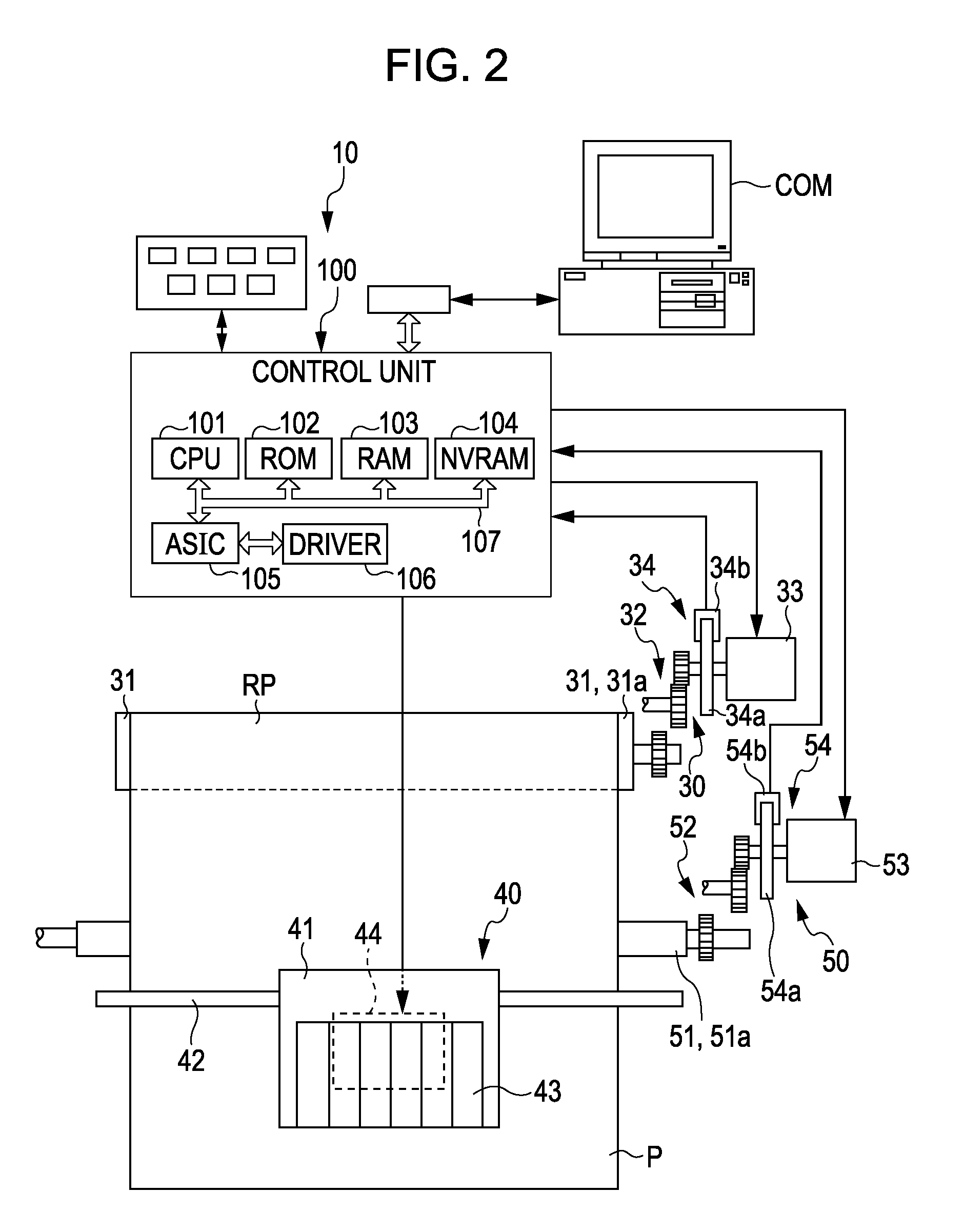
[0009]According to the above-described printing method, the driving of the second motor and ink ejecting of the print head are intermittently performed in an alternating manner. Thus, although there is a period (i.e., a period in which ink ejection is performed by the print head) in which the driving of the second motor has stopped, driving of the first motor is also stopped during at least a part of that period. Accordingly, the processing load for controlling the driving of the first motor and the power consumption of the first motor can be suppressed. In addition, when the tension applied to the printing medium at a time when the printing medium is transported by the driving of the second motor is unstable, the amount of slip in the transport operation becomes unstable, and accordingly, the amount of transport becomes incorrect. However, the above-described problem of the amount of slip does not occur in the period in which the second motor is not driven, and accordingly, the driving of the first motor can be stopped. The driving according to an embodiment of the invention represents a state in which each motor actively generates a driving force and is not limited to a state in which the driving unit of each motor is actually rotated by the driving force or the like.
[0011]On the other hand, for a case where the tension applied to the printing medium is to be decreased so as to be the designated tension, when the tension is decreased before driving of the second motor is started, transport of the printing medium can be started by smoothly using the second motor. Accordingly, it may be configured that driving of the first motor is started from a predetermined time before the start of the driving of the second motor for a case where the tension applied to the printing medium is to be decreased so as to be the designated tension. In addition, it may be configured that a second driving force, that is larger than a first driving force, is used for setting the tension at the designated tension, and is outputted to the first motor when the tension is to be decreased in advance. In such a case, the transport of the printing medium can be assisted more assuredly by the second motor.
[0012]As an example of the timing for eliminating the above-described assist by using the first motor, it may be configured that, when a driving speed of the first motor reaches a predetermined transfer speed after the driving of the first motor is started, the driving force output to the first motor is switched from the second driving force to the first driving force. Thereafter, the driving force output to the first motor is switched to the first driving force after the driving speed reaches the predetermined transfer speed, and accordingly, the above-described tension can be achieved.
[0016]On the other hand, when the tension is increased by driving the first motor for applying the designated tension to the above-described printing medium, the printing medium is placed in a low-tension state. Accordingly, the transport can be started smoothly by using the second motor without performing the above-described assist. Thus, the driving of the first motor is started simultaneously with start of the driving of the second motor. Accordingly, the driving time of the second motor can be shortened, and thereby the power consumption can be suppressed. In addition, for stopping the driving, the driving of the first motor is stopped simultaneously with the stopping of the driving of the second motor.
[0017]In addition, it is preferable that short brake is applied to the first motor in a period in which driving of the first motor is stopped. In such a case, even when an external force is applied to the printing medium by the user or the like, for example, in the period in which driving of the first motor is stopped, a large braking force can be applied, and accordingly, transport of the printing medium that is not intended can be prevented.

Problems solved by technology

However, at that moment, there are cases where the paper sheet is loosened between the roll body and the paper transporting mechanism.
When a printing process is performed using the loosened paper sheet, a printed image is disturbed so that the image quality deteriorates.
As described above, in a printer that uses the roll body, a user needs to eliminate the looseness of the paper sheet manually, and there is a problem that time is needed to eliminate the looseness of the paper sheet.
In addition, when the looseness is missed or the looseness cannot be eliminated sufficiently, the printed image may be disturbed.
In addition, when the tension applied to the printing medium at a time when the printing medium is transported by the driving of the second motor is unstable, the amount of slip in the transport operation becomes unstable, and accordingly, the amount of transport becomes incorrect.
In such a case, as the roll body freely runs, the roll body sends out the printing medium by an amount of transport that is not intended, and accordingly there is a mismatch between the amount of transport and the driving amount of the second motor.
In other words, looseness of the printing medium is generated between the roll body and the transport driving roller.
In addition, when the driving speed of the first motor is abnormally higher than that of the second motor, there is a mismatch in the amounts of transport, and looseness of the printing medium is generated.

Method used


Image

  • Printing method and printing apparatus
  • Printing method and printing apparatus
  • Printing method and printing apparatus

Examples


Embodiment Construction

[0042]Hereinafter, embodiments of the invention will be described in the following order.

[0043]1. Configuration of Printer

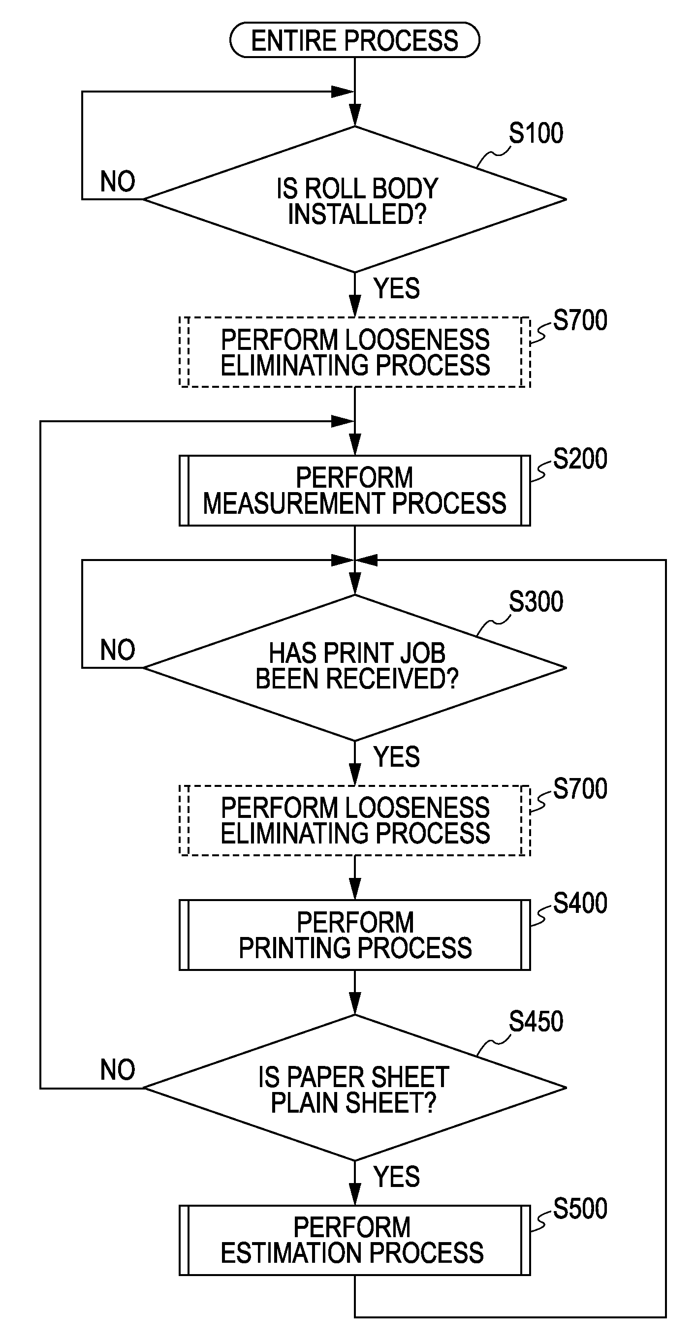
[0044]2-1. Entire Process

[0045]2-2. Measurement Process

[0046]2-3. Estimation Process

[0047]2-4. Printing Process

[0048]2-5. Roll Control Process

[0049]2-6. Looseness Eliminating Process

1. Configuration of Printer

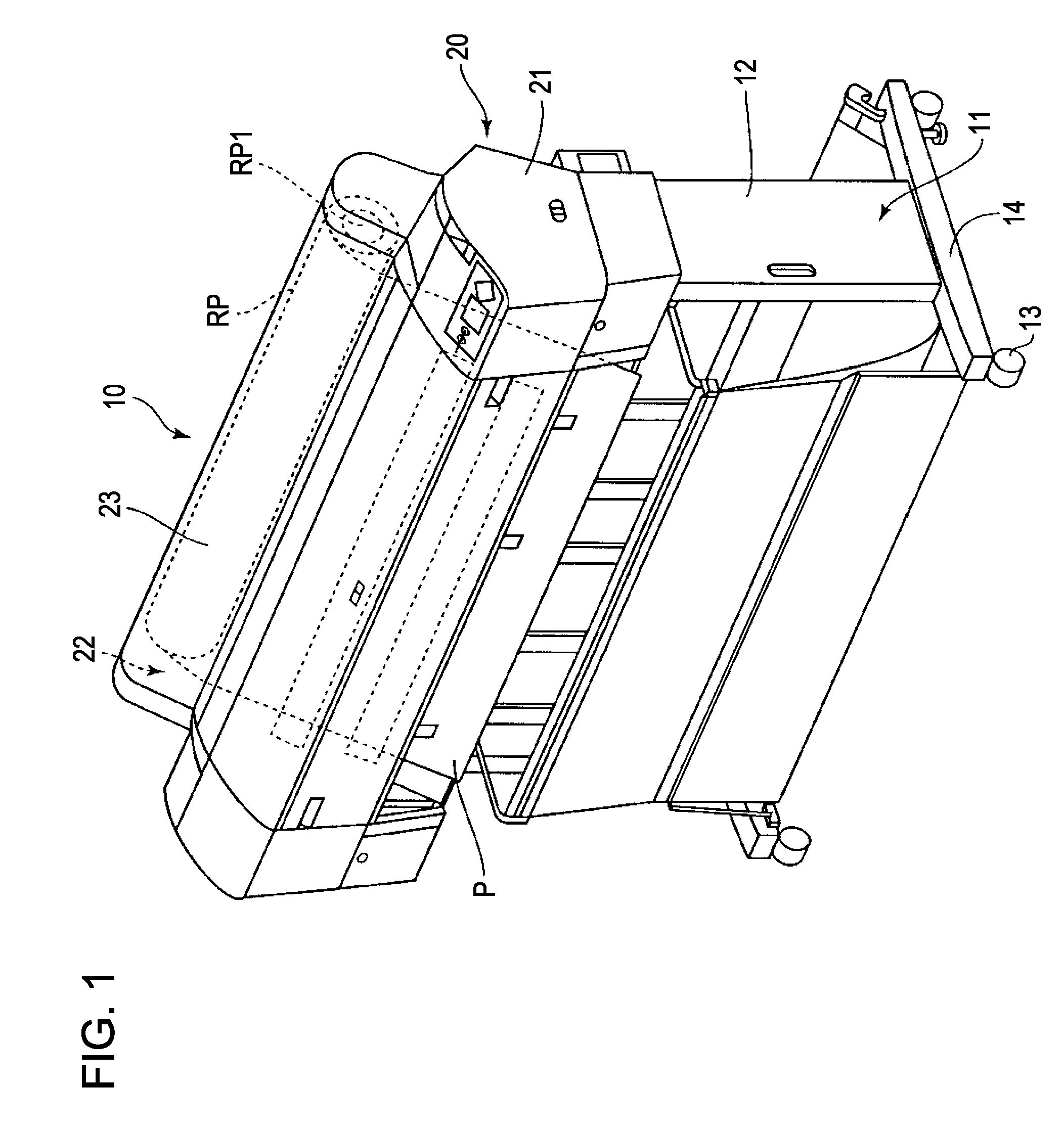
[0050]Hereinafter, a printer 10 as a printing apparatus (fluid ejecting apparatus) according to an embodiment of the invention and a control process thereof will be described. The printer 10 according to this embodiment, for example, is a printer for printing a large-sized paper sheet that is equal to or larger than A2 of the JIS standard. In addition, the printer according to this embodiment is an ink jet printer. The ink jet printer may employ any ejection method for ejecting ink. In addition, in the description below, the lower side denotes a side on which the printer 10 is mounted, and the upper side denotes a side that is apart from the side on which th...


PUM


Abstract

There is provided a printing method using a first motor that applies a driving force for rotating a roll body around which a printing medium is wound, a second motor that applies a driving force for intermittently driving a transport driving roller that transports the printing medium, and a print head that intermittently ejects ink onto the printing medium alternately with the driving of the second motor. The printing method includes driving the first motor such that tension applied to the printing medium is constant during at least a part of a period in which the second motor is driven and stopping the driving of the first motor during at least a part of a period in which the driving of the second motor is stopped.

Description

[0001]This application claims priority to Japanese Patent Application No. 2008-221958, filed Aug. 29, 2008, the entirety of which is incorporated by reference herein.BACKGROUND[0002]1. Technical Field[0003]The present invention relates to a printing method and a printing apparatus.[0004]2. Related Art[0005]Among ink jet printers, there is a type that uses large-sized paper sheets having a size that is equal to or larger than A2. In such ink jet printers used for large-sized paper sheets, a roll paper is frequently used in addition to single printing sheets. Hereinafter, it is assumed that a roll paper is acquired by winding paper into a roll body, and pulling out a part from the roll body, which is referred to as a paper sheet. The pulling of the paper sheet from the roll body is performed by driving a transport roller to rotate using a paper transporting motor (PF motor). The PF motor is controlled using PID control. An example of a printer that uses the above-described roll body i...

Claims


Application Information

Patent Timeline
Patent Type & Authority Applications(United States)
IPC IPC(8): B41J29/38
CPCB41J3/543
Inventor IGARASHI, HITOSHIHATADA, KENJI
Owner SEIKO EPSON CORP
Learn More