
Photographing apparatus and method

Active Publication Date: 2010-03-04
FUJIFILM CORP
View PDF8 Cites 20 Cited by
  • Summary
  • Abstract
  • Description
  • Claims
  • Application Information

AI Technical Summary

Benefits of technology

[0009]The present invention is made in view of the above circumstances, and has an object to provide a photographing apparatus and method capable of photographing a favorable image by automatically detecting a photographing situation where many people photograph a small number of photographic subjects, and properly guiding visual lines of the photographic subjects.
[0034]According to the present invention, the photographing situation where many people photograph a small number of photographic subjects is automatically detected, visual lines of the photographic subjects are properly guided, and a favorable image photographed at, so-called, a photographing situation that a visual line of a photographic subject faces into a camera directly can be easily photographed.

Problems solved by technology

Incidentally, in such a photographing situation that many people photograph a small number of photographic subjects, it is difficult to direct the visual line of the subjects to the photographing lens.
However, in the methods of Japanese Patent Application Laid-Open No. 2003-78792, Japanese Patent Application Laid-Open No. 2005-283931 and Japanese Patent Application Laid-Open No. 2006-33367, it is impossible to perform an operation of properly guiding the visual lines of the photographic subjects to the photographing lenses because the photographing situations cannot be discriminated.

Method used


Image

  • Photographing apparatus and method
  • Photographing apparatus and method
  • Photographing apparatus and method

Examples


first embodiment

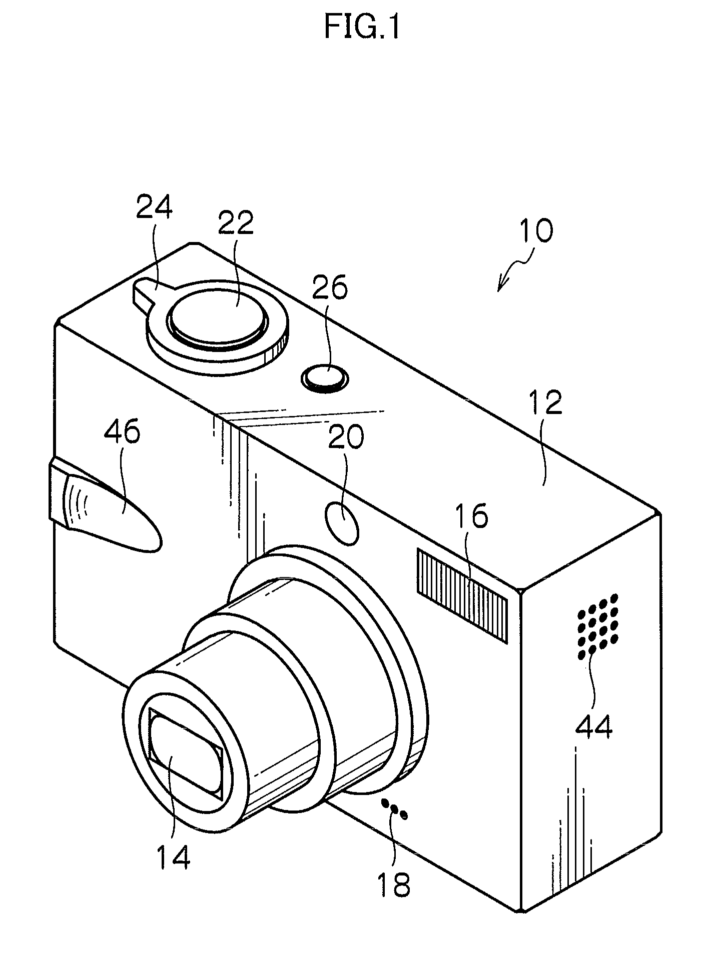
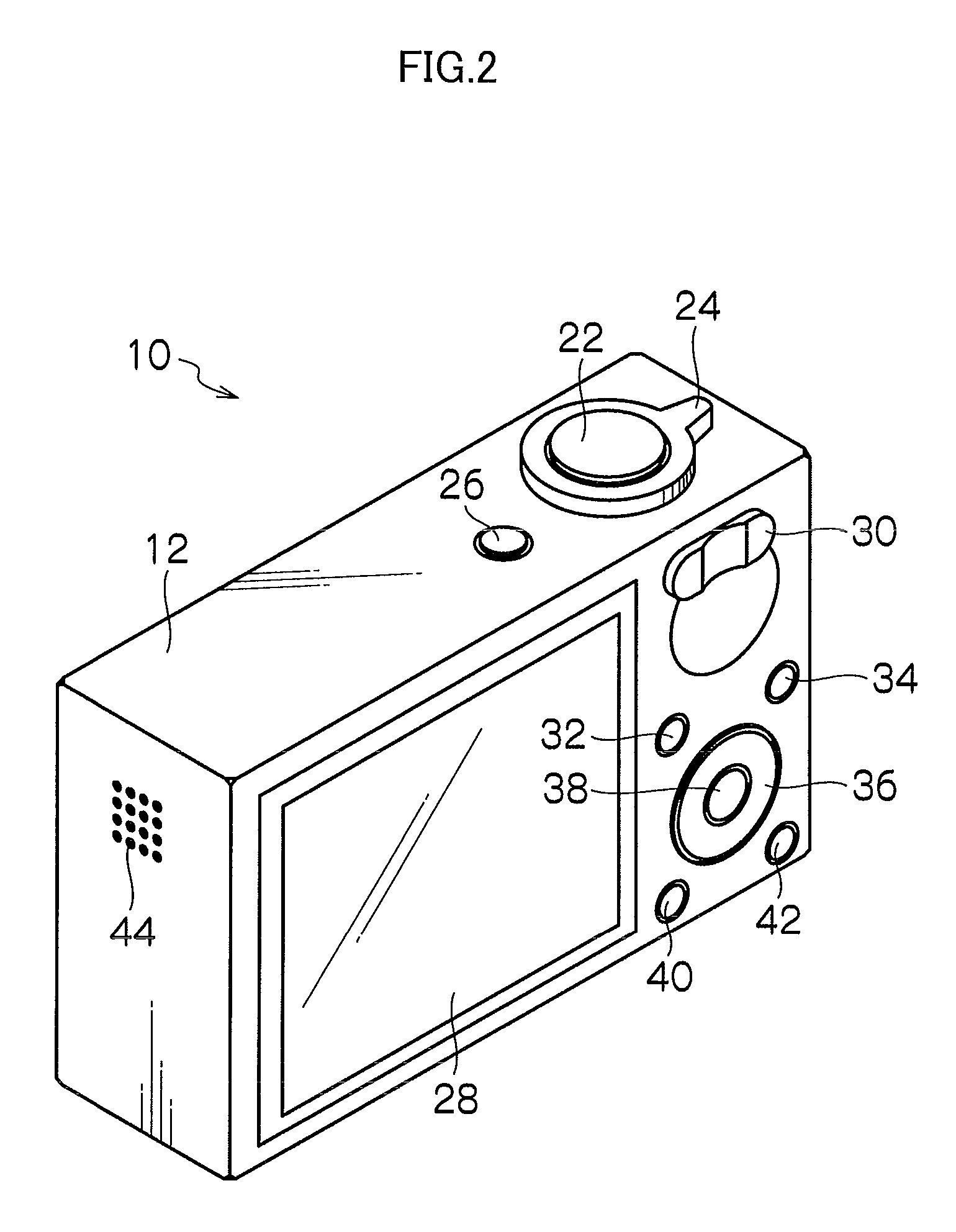
[0047]FIGS. 1 and 2 are respectively a front perspective view and a rear perspective view showing an external configuration of a digital camera to which the present invention is applied.

[0048]As shown in the FIGS. 1 and 2, a digital camera 10 is configured as a so-called compact camera, and a camera body 12 thereof is formed into the shape of a rectangular parallelepiped box with a small thickness.

[0049]As shown in FIG. 1, a photographing lens 14, a flash 16, a microphone 18 and a visual line guiding lamp 20 are provided on a front surface of the camera body 12, and a shutter button 22, a mode lever 24 and a power supply button 26 are provided on a top surface.

[0050]Meanwhile, as shown in FIG. 2, a monitor 28, a zoom button 30, a reproduction button 32, a function button 34, a cross button 36, a MENU button 38, an OK button 40 and a cancel button 42 are provided on a rear surface of the camera body 12, and a speaker 44 is provided on a lateral surface.

[0051]Further, a tripod screw h...

second embodiment

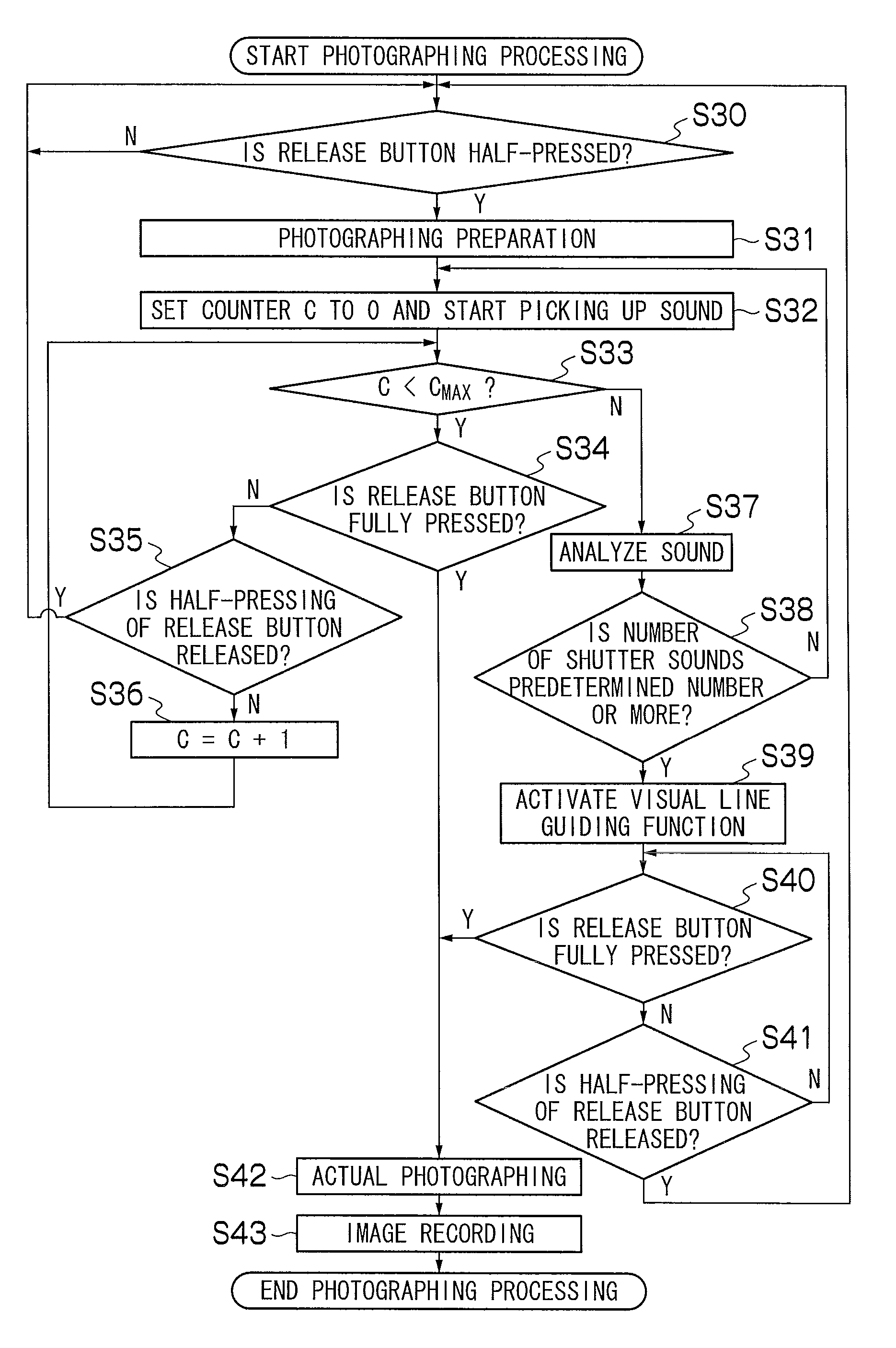
[0187]A digital camera of the present embodiment determines the photographing situation based on a shutter sound which occurs around the digital camera. Specifically, when a number of shutter sounds occur around the digital camera in a predetermined period, the photographing situation is considered to be the photographing situation where many people photograph a small number of subjects (situation of a photo session). Therefore, in such a case, the digital camera activates the visual line guiding function automatically.

[0188]FIG. 7 is a block diagram showing a system configuration of a digital camera 10a of the present embodiment.

[0189]As shown in FIG. 7, the digital camera 10a of the present embodiment differs from the digital camera 10 of the aforementioned first embodiment in the feature of including a sound detecting circuit 190. Accordingly, only the configuration of the sound detecting circuit 190 will be described here.

[0190]The sound detecting circuit 190 analyzes sound data...

third embodiment

[0214]The digital camera of the second embodiment detects the photographing situation based on the shutter sounds occurring around the digital camera. Meanwhile, the digital camera of the present embodiment detects the photographing situation by detecting voices which are frequently made in the photographing situation of a photo session, for example, “Look this way”, “I'm taking a photo” or the like.

[0215]The basic configuration of the apparatus is the same as that of the digital camera 10a of the aforementioned second embodiment, and therefore, only the determination method of the photographing situation and the procedure of processing in the case of photographing will be described.

[0216]Determination of the photographing situation is performed based on the sound picked up from the microphone 18, and when a sound which is registered in advance is detected, the photographing situation is determined as that of a photo session.

[0217]In concrete, when the shutter button 22 is half-pres...


PUM


Abstract

A photographing apparatus includes a photographing lens; an image acquisition device for acquiring an image of a subject; a recording device for recording the image acquired in accordance with an instruction of actual photographing in a recording medium; a visual line guiding device for guiding a visual line of the subject to the photographing lens; and an activation control device for activating the visual line guiding device according to a photographing situation which is determined based on the image acquired by the image acquisition device.

Description

BACKGROUND OF THE INVENTION[0001]1. Field of the Invention[0002]The present invention relates to a photographing apparatus and method, and particularly to a photographing apparatus and method for photographing a photographic subject by guiding a visual line of the photographic subject to a photographing lens by a visual line guiding device.[0003]2. Description of the Related Art[0004]In general, in photographing with persons and pets as photographic subjects, the visual lines of the subjects are preferably directed to photographing lenses (so-called a situation that a visual line of a photographic subject faces into a camera directly).[0005]Thus, Japanese Patent Application Laid-Open No. 2003-78792, Japanese Patent Application Laid-Open No. 2005-283931 and Japanese Patent Application Laid-Open No. 2006-33367 each propose guiding the visual line of a photographic subject to the photographing lens by performing an operation of calling attention of the photographic subject on the camer...

Claims


Application Information

Patent Timeline
IPC IPC(8): G06K9/46H04N7/18
CPCH04N5/23212H04N5/23219H04N2101/00H04N5/2351H04N5/23293H04N23/611H04N23/71
Inventor IZAWA, KATSUTOSHI
Owner FUJIFILM CORP
Learn More