
Electronic Apparatus with Protective Panel

a technology of electronic equipment and protective panels, which is applied in the direction of portable computer details, electric equipment casings/cabinets/drawers, instruments, etc., can solve problems such as deterioration in operational ease and efficiency, and achieve the effects of improving avoiding or restricting enlargement or deterioration in operational readiness and efficiency of electronic equipmen

Inactive Publication Date: 2010-03-04
NISSHA PRINTING COMPANY
View PDF6 Cites 100 Cited by
  • Summary
  • Abstract
  • Description
  • Claims
  • Application Information

AI Technical Summary

Benefits of technology

[0004]In recent years, some of mobile phones or “smart” phones as an example of an electronic apparatus with a protective panel, are provided with multiple functions, i.e. not only the main telephoning function, but also other functions such as an electronic mailing function, internet function, as well as such additional functions as photographing function and music playing function. In order to achieve such increasing of functions while avoiding enlargement of the electronic apparatus, it is desired that each switch should be configured to serve for multiple of purposes, thereby reducing the total number of switches to be additionally provided.

Problems solved by technology

However, if such multi-purpose configuration of switches goes to extreme, each switch is provided with too many functions, which invites deterioration in the operational ease and efficiency.
Further, as there practically exits a limit in the number of the switches provided for achieving the original functions and in the number of the switches additionally provided, further increase in the functions of the electronic apparatus will necessarily invite enlargement of this electronic apparatus.

Method used


Image

  • Electronic Apparatus with Protective Panel
  • Electronic Apparatus with Protective Panel
  • Electronic Apparatus with Protective Panel

Examples


first embodiment

[0045]Next, a first embodiment of the present invention will be described with reference to the accompanying drawings.

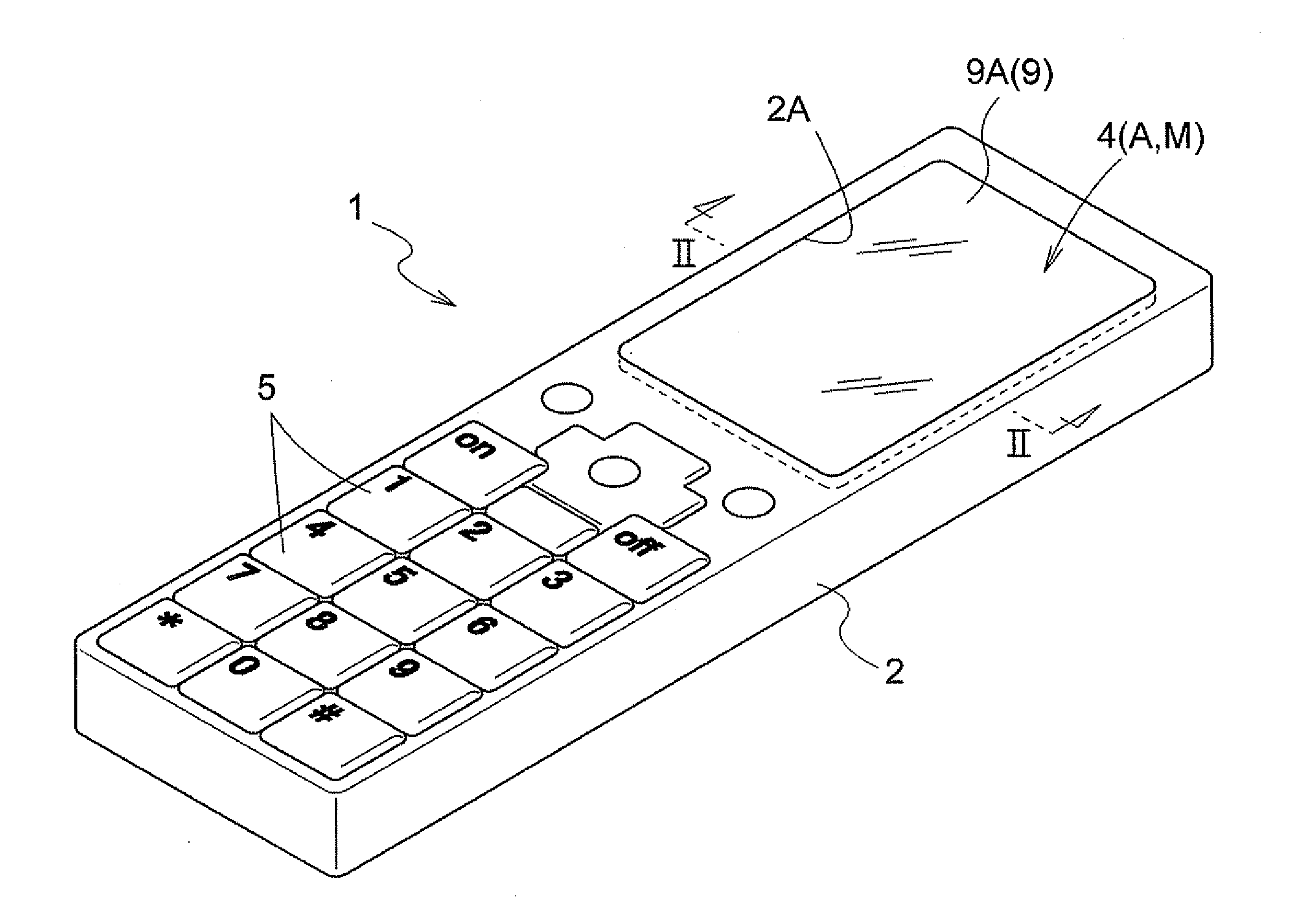
[0046]Some non-limiting examples of the electronic apparatus with a protective panel relating to the present invention are a mobile phone, a “smart” phone, a PDA, a car navigation apparatus, a digital camera, a digital video camera, a game machine, and a tablet. In this, a cell phone 1 will be explained as one example.

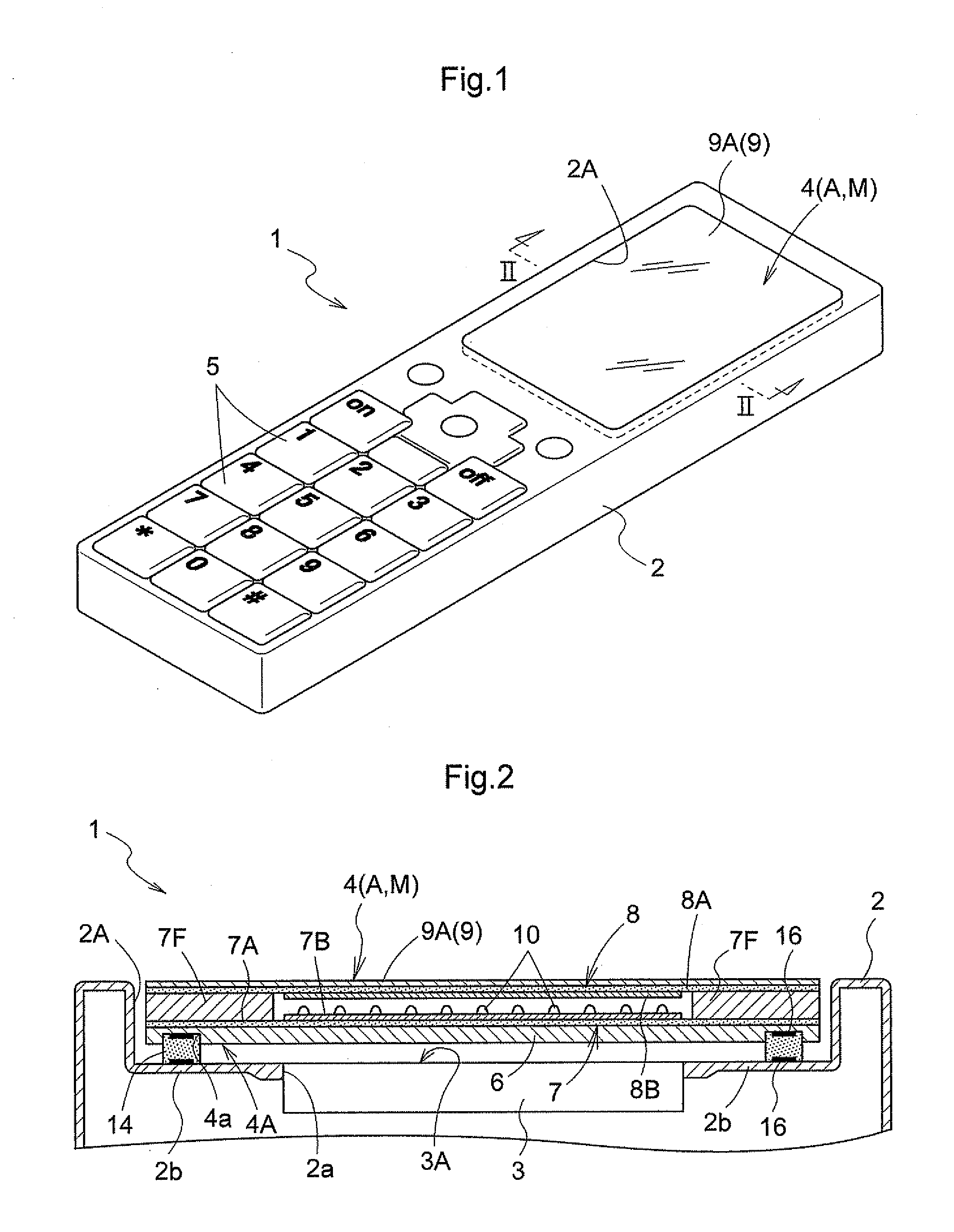
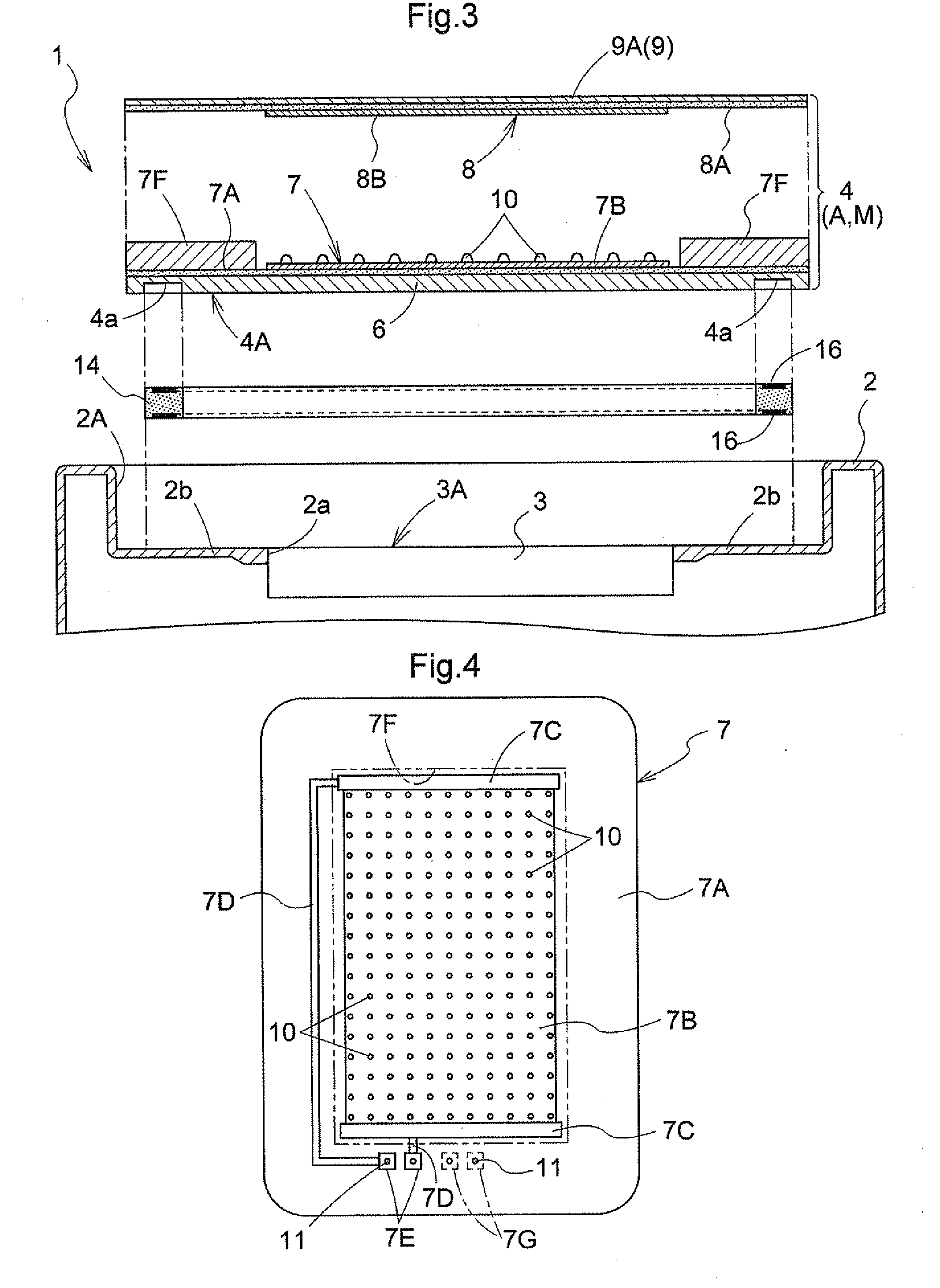
[0047]FIG. 1 is a perspective view of the cell phone 1. FIG. 2 is a cross sectional view taken along a line II-II in FIG. 1, of principal portions, showing a construction of a protective panel according to the first embodiment, FIG. 3 is an exploded perspective view showing the construction of the protective panel according to the first embodiment.

[0048]As shown in FIGS. 1-3, in this mobile phone 1 as an example of an electronic apparatus with a protective panel, includes an enclosure 2 made of a synthetic resin forming a display window 2A in its front ...

second embodiment

[0112]The electronic apparatus with a protective panel according to a second embodiment differs from that of the first embodiment in that the distance between the movable portion and the support portion where the pressure-sensitive conductive rubber is interposed is caused to increase in response to increase in the depressing force (load) by the depressing operation. Next, the electronic apparatus with a protective panel according to the second embodiment will be described, but, explanation of same constructions thereof as those in the first embodiment will be omitted.

[0113]FIG. 9 is a cross sectional view of principal portions showing the construction of a mobile phone 1 as an electronic apparatus with a protective panel according to the second embodiment. As shown, in the case of the cell phone 1 of the second embodiment too, the movable portion M is comprised of the protective panel 4. The enclosure 2 consists of a main body 21 and a lid portion 22 and the main body 21 and the li...

third embodiment

[0115]The electronic apparatus with a protective panel according to a third embodiment differs from those of the first and second embodiments in that the movable portion is comprised of the protective panel and the display device. Next, the electronic apparatus with a protective panel according to the third embodiment will be described, but, explanation of same constructions thereof as those in the foregoing embodiments will be omitted.

[0116]FIG. 11 is a cross sectional view of principal portions showing the construction of a cell phone 1 as an electronic apparatus with a protective panel according to the third embodiment. As shown, in the case of the cell phone 1 of the third embodiment, the movable portion M includes the protective panel 4 and the display device 3. Specifically, the back face of the protective panel 4 and the front face of the display section 3A are bonded to each other with a transparent adhesive agent. As the protective panel 4 is formed larger in area than the ...


PUM


Abstract

An electronic apparatus with a protective panel, includes a display device 3 having a display section 3A, an enclosure 2 having a display window 2A which is open in one direction and mounts therein the display device 3 so as to expose the display section 5A to the outside, a protective panel 4 disposed at the display window 2A so as to cover the display section 3A from the outside; and a pressure-sensitive conductive rubber 14 interposed between a movable portion M including at least the protective panel 4 of the protective panel 4 and the display device 3 and a frame-like support portion 2b defined by a surface of the enclosure 2 within the display window 2A, so as to prevent intrusion of foreign substance to the interior of the enclosure 2 through the display window 2A, the rubber detecting a depressing operation on the movable portion M.

Description

TECHNICAL FIELD[0001]The present invention relates to an electronic apparatus with a protective panel, wherein an enclosure mounting a display device therein forms a display window for exposing a display section of the display device to the outside, the display window includes a support portion for supporting the protective panel for the display device, with the protective panel being fitted within the display window.BACKGROUND ART[0002]Conventionally, in the case of an electronic apparatus with a protective panel described above, the enclosure mounting the display device therein forms a recess. In a bottom face of this recess of the enclosure, there is defined an aperture for exposing the display section of the display device to the outside. The protective panel for the display device is fitted within the recess, in such a manner that the peripheral edge portion of the protective panel is supported directly to the peripheral edge of the bottom face of the recess (see, e.g. Patent D...

Claims


Application Information

Patent Timeline
Patent Type & Authority Applications(United States)
IPC IPC(8): H05K5/02G06F3/041
CPCG06F1/1626G06F1/1637G06F2203/04105G06F3/041G06F1/169G06F3/045G06F3/04142G06F3/0412G06F3/0414H05K5/0204
Inventor NISHIKAWA, KAZUHIROKAI, YOSHIHIROTAKAI, YUICHIRO
Owner NISSHA PRINTING COMPANY
Learn More