Screenless internals for radial flow reactors

a radial flow reactor and internal technology, applied in the direction of chemical apparatus and processes, physical/chemical process catalysts, chemical/physical processes, etc., can solve the problems of corroded screens, corroded meshes or screens used to hold catalyst beds in place, and screen often undergoes some reaction

Inactive Publication Date: 2010-03-04
UOP LLC
View PDF20 Cites 4 Cited by
  • Summary
  • Abstract
  • Description
  • Claims
  • Application Information

AI Technical Summary

Benefits of technology

[0008]Other objects, advantages and applications of the present invention will become apparent to those skilled in the art from the following drawings and detailed description.

Problems solved by technology

The screen is preferably constructed of a non-reactive material, but in reality the screen often undergoes some reaction through corrosion, and over time problems arise from the corroded screen or mesh.
A significant problem is the corrosion of meshes or screens used to hold catalyst beds in place, or for the distribution of reactants through a reactor bed.
Corrosion can plug apertures to a screen or mesh, creating dead volumes where fluid does not flow.
Corrosion can also create larger apertures where the catalyst particles can then flow out of the catalyst bed with the fluid and be lost to the process increasing costs.
This produces unacceptable losses of catalyst, and increases costs because of the need to add additional makeup catalyst.
The design of reactors to overcome these limitations can save significantly on downtime for repairs and on the loss of catalyst, which is a significant portion of the cost of processing hydrocarbons.

Method used


Image

  • Screenless internals for radial flow reactors
  • Screenless internals for radial flow reactors
  • Screenless internals for radial flow reactors

Examples


Embodiment Construction

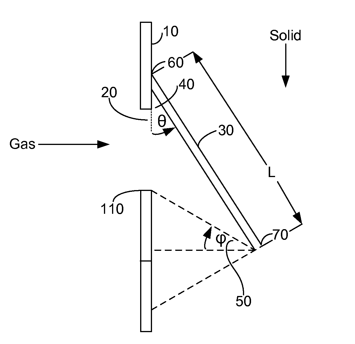
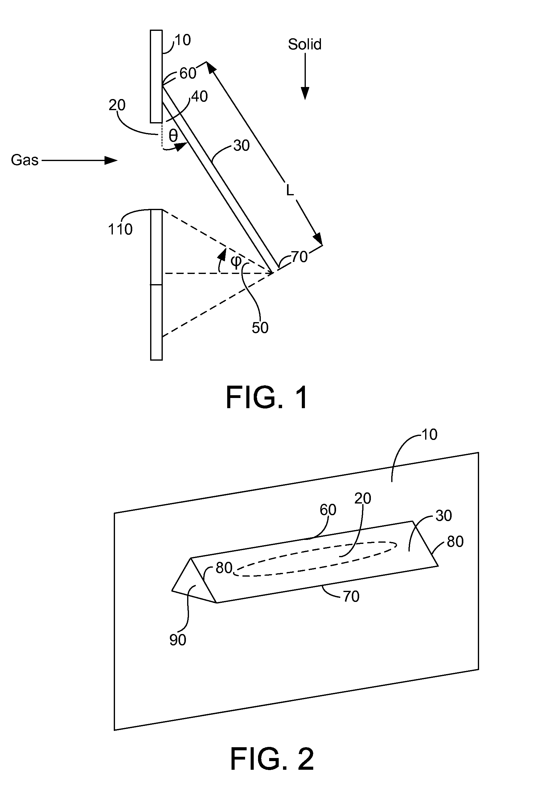
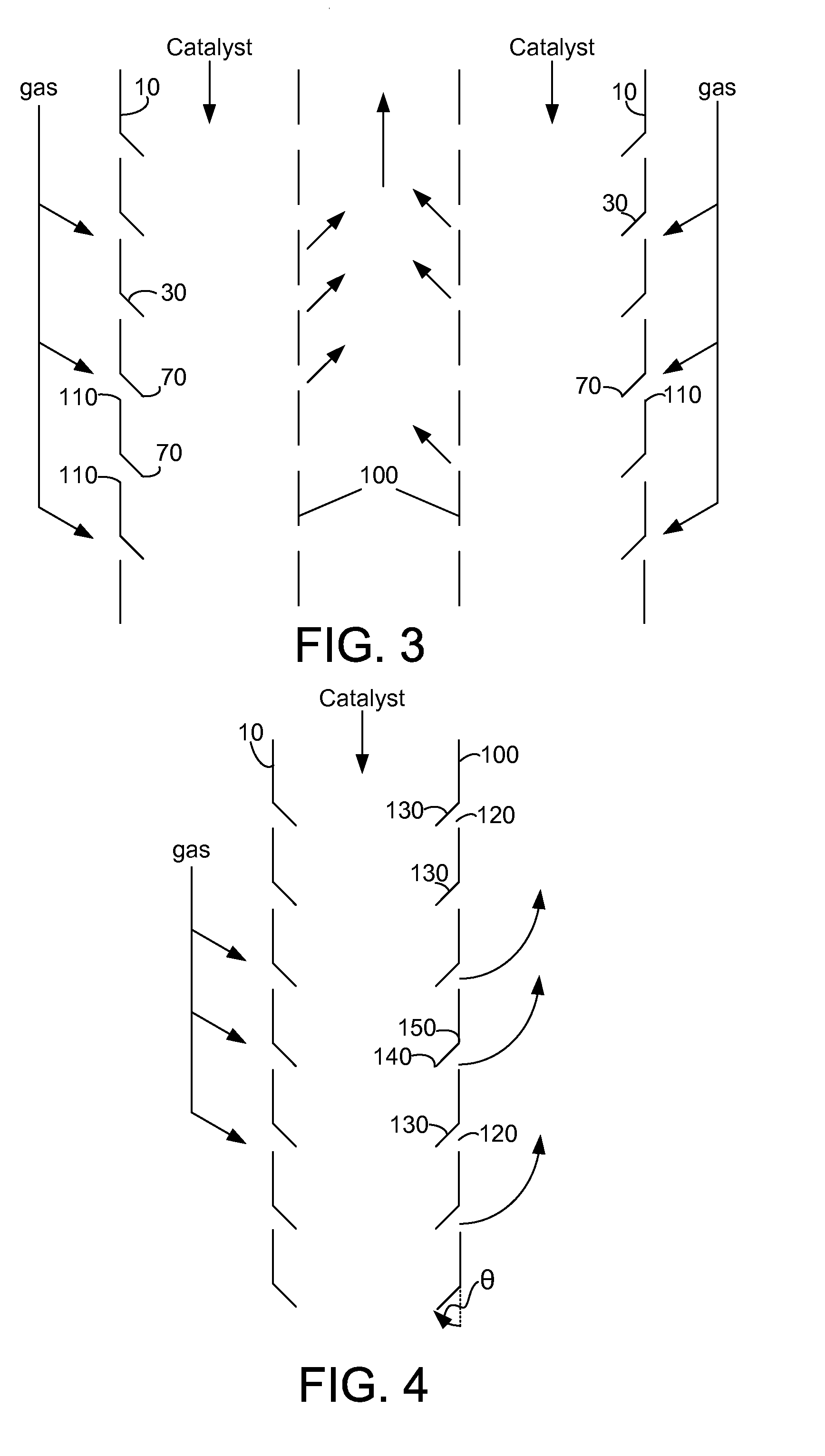
[0017]A problem exists with radial flow reactors where a catalyst flows down an annular region, and the annular region is defined by an inner screened partition and an outer screened partition, which defines the catalyst bed, or a particle retention volume for holding a granular solid. A fluid, usually a gas, flows across the partitions and catalyst bed, reacting with the catalyst to produce a product fluid, also usually a gas. The reactor holds the catalyst in with screens where the gas flows through. The screened partitions need holes sufficiently small to prevent catalyst particles from passing, but the holes are subject to plugging and creating dead spaces where the gas doesn't flow, as well as the partitions are subject to erosion and corrosion, creating holes that allow for catalyst to spill out.

[0018]The apparatus can also be an adsorber for adsorbing a constituent from the fluid flowing over a granular solid adsorbent. This includes an apparatus where the adsorbent is loaded...


PUM

PropertyMeasurementUnit
angleaaaaaaaaaa
angleaaaaaaaaaa
angleaaaaaaaaaa

Abstract

An apparatus for contacting a bed of particulate material with a cross flowing fluid, which maintains the bed of particulate material within a retention volume. The apparatus includes partitions for retaining particles, with apertures disposed within the partitions. The apertures are covered by louvers that extend above the edges of the apertures to prevent solid particles from spilling through inlet apertures.

Description

CROSS-REFERENCE TO RELATED APPLICATION[0001]This application is a Division of copending Application No. 11 / 458,402 filed Jul. 19, 2006, the contents of which are hereby incorporated by reference in its entirety.FIELD OF THE INVENTION[0002]This invention relates to the field of fluid particle contact and to an apparatus for contacting fluids and particles. More specifically, this invention relates to a moving bed of particles with a cross-flowing fluid.BACKGROUND OF THE INVENTION[0003]A wide variety of processes use radial flow reactors to provide for contact between a fluid and a solid. The solid usually comprises a catalytic material on which the fluid reacts to form a product. The processes cover a range of processes, including hydrocarbon conversion, gas treatment, and adsorption for separation.[0004]Radial flow reactors are constructed such that the reactor has an annular structure and that there are annular distribution and collection devices. The devices for distribution and c...

Claims


Application Information

Patent Timeline
Patent Type & Authority Applications(United States)
IPC IPC(8): B01J8/02
CPCB01J8/008B01J8/085B01J8/12B01J8/06
Inventor GLOVER, BRYAN K.WOODLE, GUY B.ZIMMERMANN, JOSEPH E.SENETAR, JOHN J.
Owner UOP LLC
Why Eureka
Try Eureka