Unlock instant, AI-driven research and patent intelligence for your innovation.

Method for providing a utensil with a decoration

a technology for providing utensils and decorations, applied in the directions of instruments, other domestic objects, transportation and packaging, etc., can solve the problems of high processing costs and therefore cannot be applied to iron soles, and achieve the effect of higher resolution

Inactive Publication Date: 2010-03-04
KONINKLIJKE PHILIPS ELECTRONICS NV
View PDF9 Cites 7 Cited by
  • Summary
  • Abstract
  • Description
  • Claims
  • Application Information

AI Technical Summary

Benefits of technology

[0011]However, in order to better control the thickness of the layer, screen printing is a more accurate technique. In the present invention the layer is preferably obtained from a concentrated prepolymarized sol-gel precursor. By using such concentrated prepolymarized sol-gel precursor the amount of shrinking during curing is reduced considerably. The reduced amount of shrinking permits the use of accurate screen-printing technique to apply the layer on a substrate.
[0016]Subsequently the sol-gel precursor is embossed to create an optical interference grating by placement of a flexible stamp. The flexible stamp can e.g. be a rubber stamp. A preferred rubber suitable for the stamp is a silicone based rubber like polydimethylsilane (PDMS). Silicone based rubber have the advantage that most of the solvents used for the precursors are absorbed by the silicon rubber of the stamp, which facilitates the sol-gel layer to solidify before the stamp is removed. If the sol-sel layer is solidified by means of UV, the stamp should be translucent as well. There are several principles for transferring a pattern from a stamp to a sol-gel layer.
[0017]The first printing principle comprises pressing stamp and sol-gel layer against each other, wherein the stamp and the sol-gel layer contact each other through a plane. An important advantage of this first printing principle is that the alignment of the stamp and the sol-gel layer with respect to each other can be performed very accurately. An important disadvantage of this printing principle is that on moving of the stamp and the sol-gel layer towards each other, air may be entrapped between the sheets. As a result, the transfer of the pattern may be incomplete. However, this disadvantage can be overcome by carrying out the procedure as described above under a reduced pressure. The pressure should then be reduced to a pressure slightly above the vapour pressure of the solvent in the sol-gel layer. Embossing under a reduced pressure is particular advantageous at curved surfaces.
[0018]A second printing principle is described in WO 03 / 099463, and comprises the following steps: positioning the stamp and the sol gel layer with respect to each other, in such a way that the stamping surface and the receiving surface face each other; fixing the positions of the stamp and the sol gel layer with respect to each other in a direction in which the receiving surface extends; moving a first portion of at least one of the stamping surface and the receiving surface forward in a direction substantially perpendicular to the receiving surface, such that a first transfer area is created between the stamping surface and the receiving surface, in which the stamp is able to locally transfer the pattern to the sol gel layer; and subsequently moving a second portion of at least one of the stamping surface and the receiving surface forward in a direction substantially perpendicular to the receiving surface, such that an enlarged transfer area is created between the stamping surface and the receiving surface, in which the stamp is able to locally transfer the pattern to the sol gel layer. By this method it is possible to control the movements of the portions of the stamping surface in such a way that a pattern on the receiving surface can be obtained, without the inclusion of air. The stamp may be moved backward after the embossed sol-gel layer is solidified to en extend that the embossed structure of the grating is maintained.
[0025]The high refractive coating may be provided with a transparent, non-scattering topcoat to obtain the desired flat surface, and protects the grating structure against mechanical damaging. The topcoat is preferably as transparent and non-scattering as possible to ensure the light that reaches the grating can interfere and that the light reflecting from the grating is not blurred due to scattering. If the topcoat scatters the incoming light the optical effect of the grating will be less.

Problems solved by technology

These are expensive processing steps and can therefore not be applied to iron soles.

Method used


Image

  • Method for providing a utensil with a decoration
  • Method for providing a utensil with a decoration
  • Method for providing a utensil with a decoration

Examples


example 1

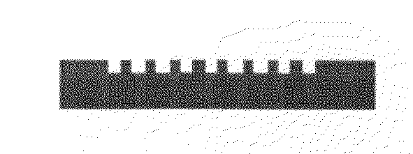
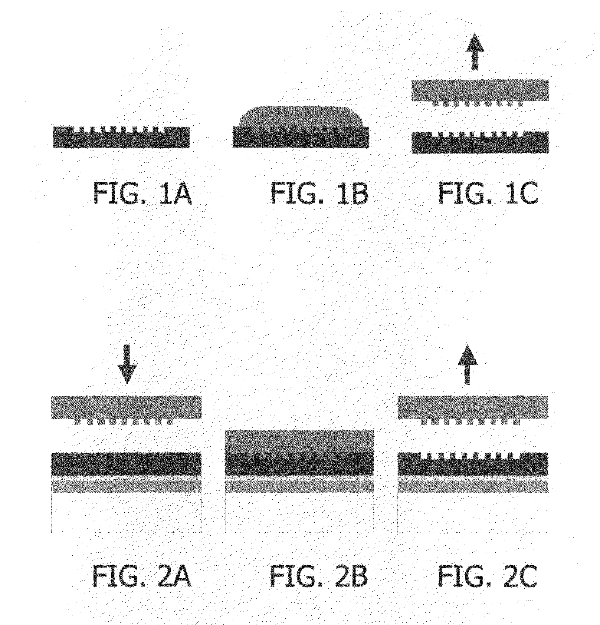
[0037]A glass-filled polyamide shaver unit is coated with a decoration according to the invention. Therefore 11.8 g of the hydrolytically condensable compound 3-glycidoxy propyl trimethoxysilane (Fluke) and 2.7 g water are stirred for 1 hour, thereby forming a sol-gel solution. Next, 3.28 g Al(O-sec-Bu)3 are mixed with 1.75 g ethyl acetoacetate (Aldrich). The resultant aluminum compound is added to the sol-gel solution, which results in the formation of a clear solution. The resultant lacquer is applied to the housing 2 by means of spraying. An optical grating was applied with a PDMS stamp. The coating was cured for 20 minutes at 80° C. and the stamp was removed.

example 2

[0038]A black sol-gel is prepared by the following method: A Sol A is made by mixing 7.9 parts of MTMS with 36.5 parts ethanol and adding this mixture to 100 parts of Ludox AS-40. After hydrolysis for 5 minutes of sol A, the following components are added: 95.3 parts of MTMS, 1.8 TFOS, 29.9 alumina CR-6, 4.5 Heucodor Black 100-9 and 18.3 parts of ethanol. The thus formed sol B is hydrolysed for 5 minutes. Sol C is prepared by adding 1.76 parts of maleic acid to sol B and hydrolysed for 45 minutes under vigorous stirring. All parts are parts in weight.

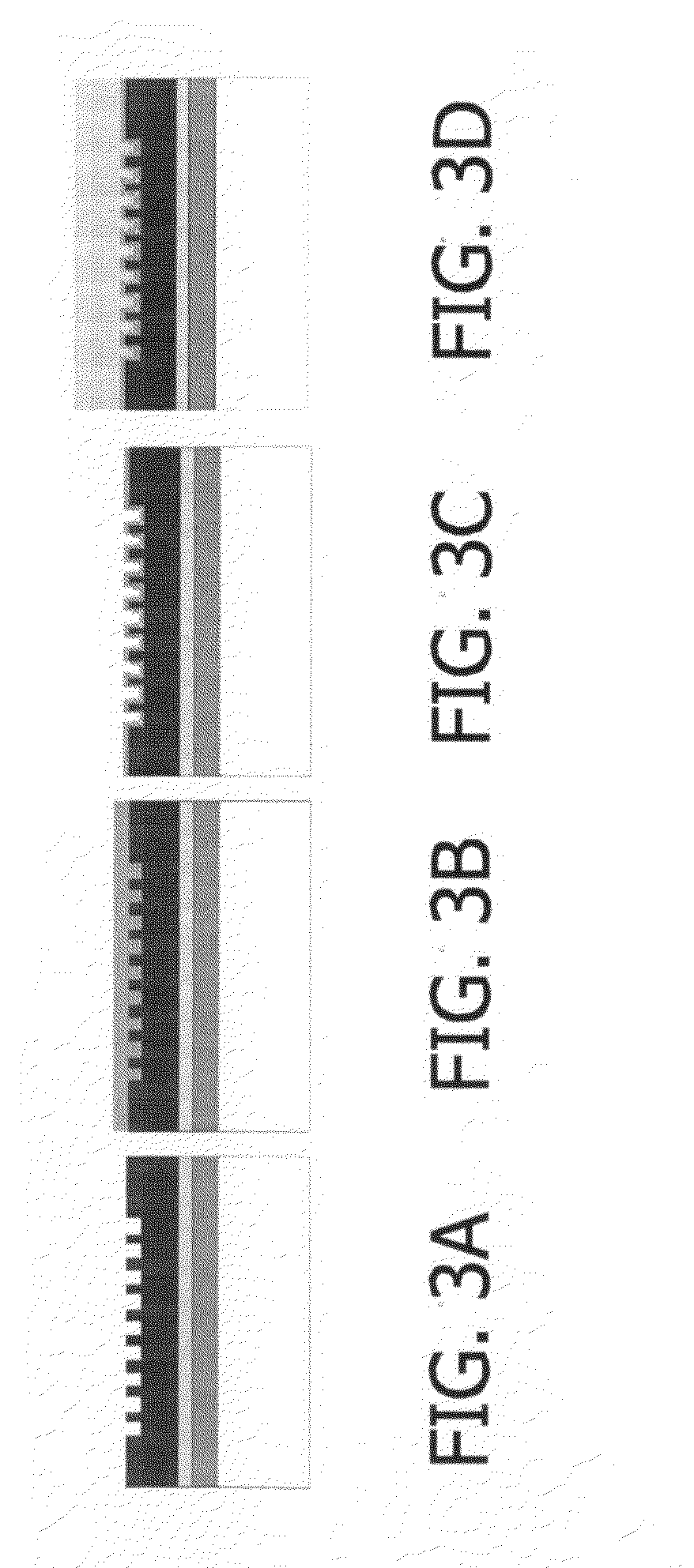
[0039]An anodised aluminium disk was coated with the thus obtained black pre coat, which was subsequently cured at 250° C. The black coating was given a UV-ozone treatment during 10 minutes to oxidise its surface and make this hydrophilic. This ensures a good adhesion for the next layer. Subsequently a transparent sol-gel layer was applied, which was structured by embossing. A transparent sol-gel layer may have the following composition...


PUM

PropertyMeasurementUnit
Flexibilityaaaaaaaaaa
Transparencyaaaaaaaaaa
Wavelengthaaaaaaaaaa

Abstract

The invention relates to a method for providing a utensil with a decoration by means of an optical interference grating. The utensil is provided with a sol-gel precursor which is embossed with a flexible stamp to create an optical interference grating. The interference grating can be provided with a second precursor of a material with an index of refraction higher than that of the sol-gel layer, and provided with a transparent, non-scattering topcoat. The invention further relates to an appliance, e.g. an iron or a shaver, coated with an organosilane layer provided with an optical interference grating.

Description

BACKGROUND OF THE INVENTION[0001]The invention relates to a method for providing a utensil with a decoration. A decoration in this application is understood to be an ornament, but it can also be a picture, a figure, or a text. Utensils, and in particular utensils for personal care may be provided with a coating of lacquer. It has been found that many compositions for personal care contain ingredients which may corrode the coating of lacquer. Particularly shaving lotions, such as preshaves and aftershaves, are found aggressive relative to the coating of lacquer. A good resistance to acids, bases and solvents is obtained by a coating of lacquer that contains a network of a hydrolytically condensed organosilane compound. Coatings of lacquer that contain a network of a hydrolytically condensed organosilane compound are known per se. These materials are typically obtained by means of a sol-gel process.[0002]In order to give the utensil an attractive e.g. metallic appearance the coating m...

Claims


Application Information

Patent Timeline
IPC IPC(8): C09D183/06B29D11/00B32B9/04
CPCB44C1/24B44C5/00B44F1/10G02B5/1852Y10T428/31663
Inventor VERSCHUUREN, MARCUSPEETERS, MARTINUS PETRUS JOSEPHWERKMAN, PETER JOHANNESSURIANTO, JENFRY
Owner KONINKLIJKE PHILIPS ELECTRONICS NV