Supercharge Your Innovation With Domain-Expert AI Agents!

Ground anchors

a technology for ground anchors and bolts, which is applied in the direction of anchoring bolts, cables for vehicles/pulleys, bulkheads/piles, etc., to achieve the effect of improving the type of anchors

Inactive Publication Date: 2010-03-11
PLATIPUS ANCHORS LTD
View PDF21 Cites 5 Cited by
  • Summary
  • Abstract
  • Description
  • Claims
  • Application Information

AI Technical Summary

Benefits of technology

"The present invention aims to improve anchors of the winged type in several ways. The invention provides a ground anchor with a central hollow tubular body portion and a pair of laterally projecting wings that are bent at an angle to the horizontal plane and a portion of the edge of each wing is also bent at an angle to the plane of the wing. The edges of the wings are rounded. The anchor has a driving edge at a leading end and a keel member formed on the body portion. The keel member is either a convergent or a socket. The technical effects of the invention include improved stability, better resistance to lateral loads, and increased efficiency in ground penetration."

Problems solved by technology

As the surface area of these anchors is not particularly large, they are not appropriate for some uses where a particular degree of strength and resistance to removal from the ground is required.

Method used


Image

  • Ground anchors
  • Ground anchors
  • Ground anchors

Examples


Embodiment Construction

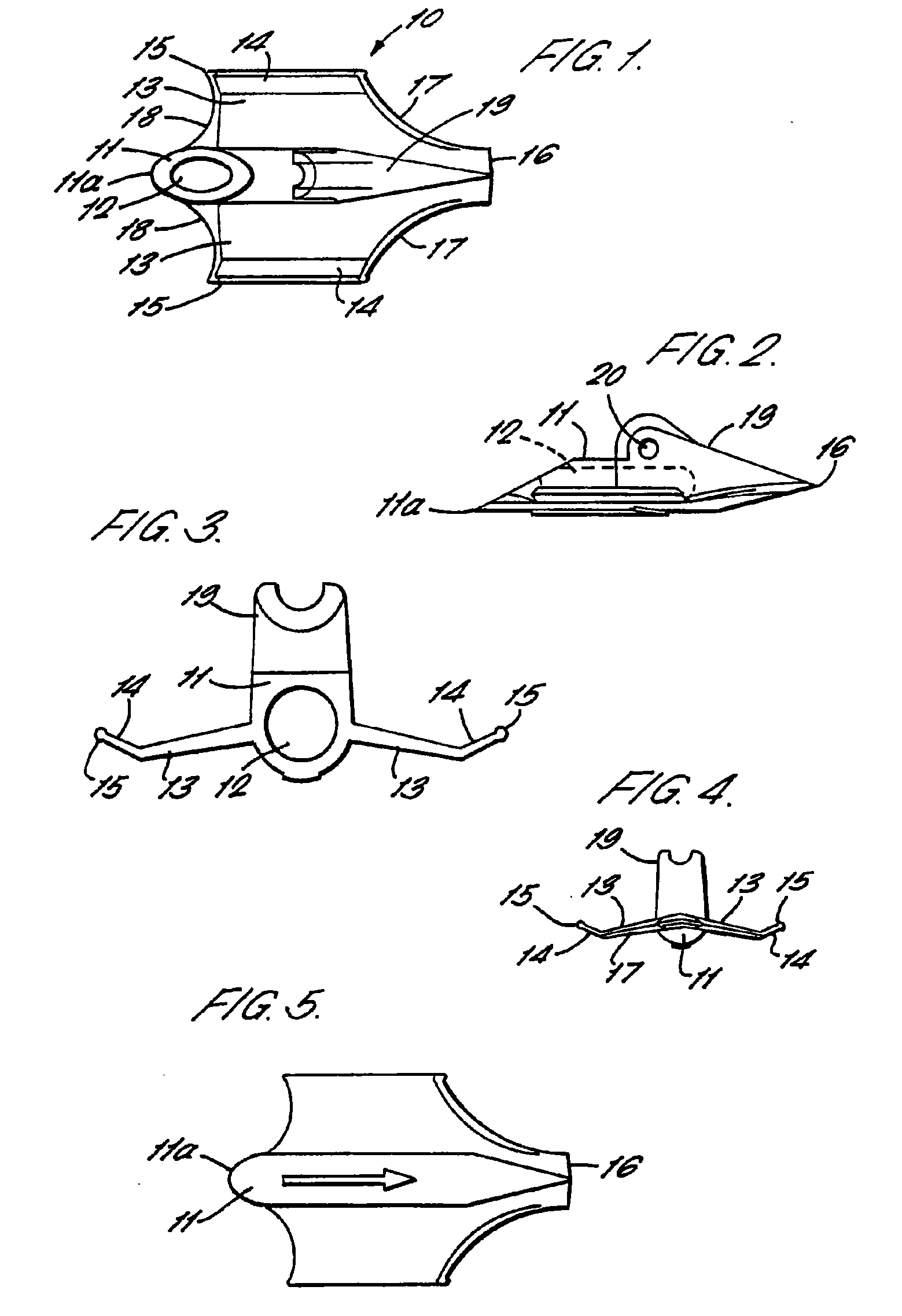
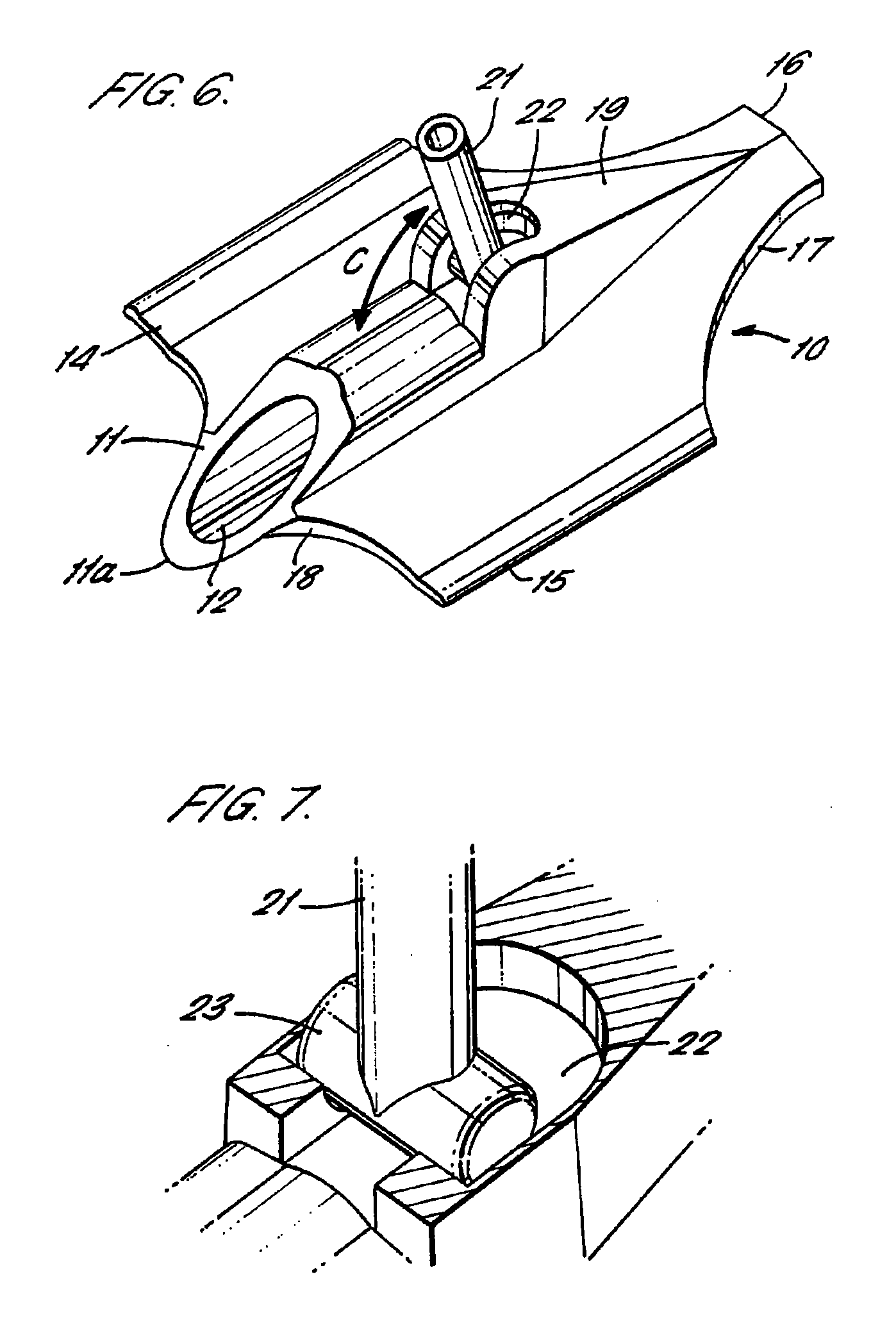
[0023]The anchor 10 comprises a central substantially tubular body portion 11 having a blind bore 12 running axially thereof for receiving a driving tool.

[0024]Projecting from each side of the body portion 11 is a wing 13. These wings 13 project upwardly or downwardly at an angle to a horizontal plane through the anchor 10. At the side edges of the wings 13 are angled winglets 14 which project at an angle to the plane of the wings 13. The edges of the angled winglets 14 are provided with rounded edge beads 15.

[0025]At one end of the anchor 10, i.e. the leading end as the anchor is driven into the ground, the wings 13 meet at a flattened driving edge 16 which may be sharpened to a chisel point. The leading wing edges 17 which connect to the driving edge 16 may also be sharpened.

[0026]At an opposite end of the anchor 10, i.e. the trailing end as the anchor is driven into the ground, the trailing edges 18 of wings 13 may curve gently in an upwardly direction. At the trailing end of the...


PUM


Abstract

The ground anchors of the type which are attached to cables, rods and the like, which are driven into the ground and tilted transversely of the hole by tensioning the cable are provided. A ground anchor including a central hollow tubular body portion extending substantially along the length of the anchor and a pair of laterally projecting wings extending from opposing sides of the body portion, wherein the wings are bent at an angle to the horizontal plane, and a portion of an edge of each wing is bent at an angle to the plane of the wing.

Description

CROSS REFERENCE TO RELATED APPLICATIONS[0001]This application is a continuation of U.S. application Ser. No. 08 / 648,079 filed on Aug. 5, 1996, which is a national stage entry under 35 U.S.C. §371 of International Application No. PCT / GB94 / 01065 filed on May 18, 1994, which claims the benefit of Great British Application No. GB9322640.5 filed on Nov. 3, 1993.BACKGROUND OF THE INVENTION[0002]1. Field of the Invention[0003]The invention relates to ground anchors of the type which are attached to cables, rods and the like, which are driven into the ground and tilted transversely of the hole by tensioning the cable.[0004]2. Description of Related Art[0005]A variety of ground anchors already exist including tubular anchors, such as those described in GB-A-1555580 and EP-A-0208153. These anchors are driven into the ground and then rotated to a horizontal locked position. As the surface area of these anchors is not particularly large, they are not appropriate for some uses where a particular...

Claims


Application Information

Patent Timeline
Patent Type & Authority Applications(United States)
IPC IPC(8): E02D5/80E02D5/74F16G11/00F16G11/10
CPCE02D5/74F16G11/10F16G11/00E02D5/80F16G11/02
Inventor AGG, CHARLES SIMON JAMES
Owner PLATIPUS ANCHORS LTD
Features
  • R&D
  • Intellectual Property
  • Life Sciences
  • Materials
  • Tech Scout
  • Unparalleled Data Quality
  • Higher Quality Content
  • 60% Fewer Hallucinations
Learn More