Piezoelectric pressure transducer

a technology of pressure transducer and piezoelectric, which is applied in the direction of capacitors, instruments, electrical equipment, etc., can solve the problems of high increased construction and production engineering costs, and inability to meet the requirements of measurement elements, etc., to achieve simple and exact, simple and thus cost-effective design

Active Publication Date: 2010-03-11
PIEZOCRYST ADVANCED SENSORICS
View PDF5 Cites 24 Cited by
  • Summary
  • Abstract
  • Description
  • Claims
  • Application Information

AI Technical Summary

Benefits of technology

[0007]This object is attained according to the present invention with a pressure transducer of this type in that the electrode sheet or each electrode sheet wraps conductively and positively as well as in a manner fixing the layers around a contact pin projecting outwards. Thus initially the layer fixing of the electrode sheet, which is very important for a reproducible quality, at the same time as the contacting of the pole of the measuring element or the measuring elements attached there is solved in a surprisingly simple and exact manner, which permits a very simple and thus cost-effective design of the pressure transducer without the necessity of further fitting elements or the like.
[0008]In a preferred embodiment of the invention at least one of the measuring elements can thereby be fixed directly on an associated electrode sheet, preferably by means of bonding, soldering or thermocompression. A positive position fixing of the mechanical unit of measuring element and electrode sheet is thus possible at the same time as the contacting of the one pole of the measuring element, which further simplifies in particular the production and assembly of a pressure transducer of this type in an advantageous manner.
[0009]In a further preferred embodiment of the invention, the second pole of the measuring element is thereby contacted via the housing base part and / or the diaphragm, which represents a further simplification and completely avoids additional expenditure in this respect.

Problems solved by technology

Although the design of pressure transducers of this type is basically very simple, the contacting of the two poles and the positioning of the measuring elements in particular require a relatively high expenditure in terms of construction and production engineering, which has hitherto prevented a mass production at low cost desirable for many applications.
However, the exact positioning with respect to the housing is thereby also carried out by means of additional elements, which furthermore entails additional expenditure in terms of construction and production engineering.

Method used


Image

  • Piezoelectric pressure transducer
  • Piezoelectric pressure transducer
  • Piezoelectric pressure transducer

Examples


Embodiment Construction

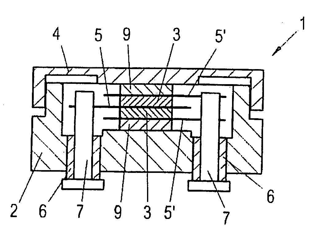
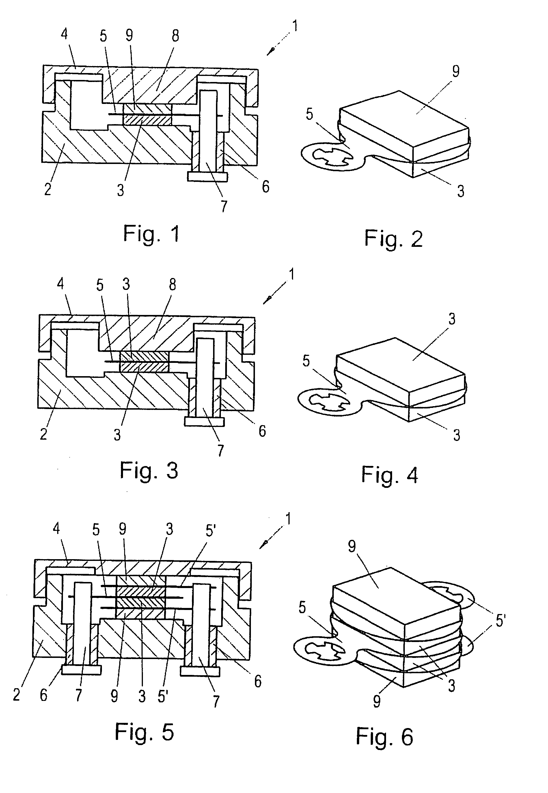
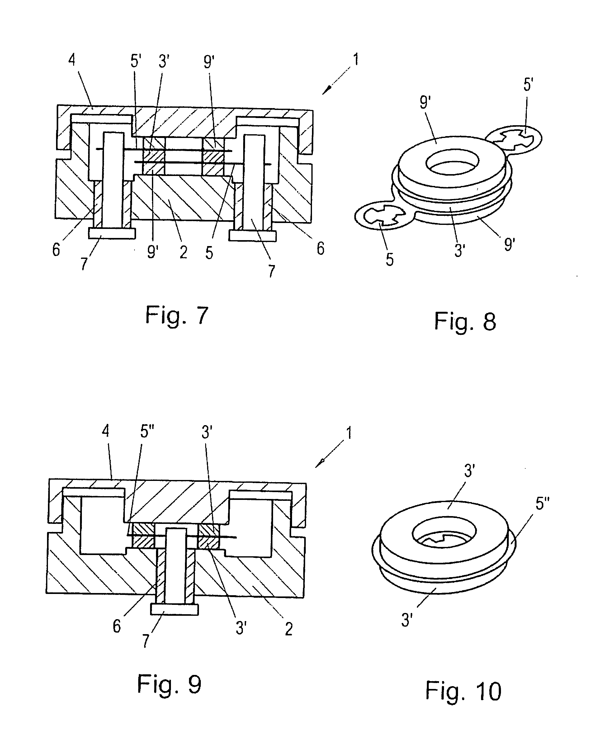
[0021]All of the exemplary embodiments represented show piezoelectric pressure transducers 1 with at least one piezoelectric measuring element 3 arranged on a housing base part 2, which measuring element itself can also be composed of several connected layers and on the side opposite the base part 2 is connected to a diaphragm 4 sealing the base part 2 and exposed to the pressure to be measured, and is electrically connected externally in a double-pole manner. The pressure acting on the diaphragm 4 from outside is transmitted as a force to the measuring element 3, which according to the known piezoelectric principle provides a charge to both poles, which charge is proportional to the pressure and capable of being tapped and further used.

[0022]According to FIGS. 1 through 13, the measuring element 3 is fixed to an electrode sheet 5, for example, through bonding soldering or thermocompression, with contact of one of its poles, which electrode sheet wraps around a contact pin 7 conduct...


PUM

PropertyMeasurementUnit
pressureaaaaaaaaaa
piezoelectricaaaaaaaaaa
conductiveaaaaaaaaaa

Abstract

To render possible a high-quality, yet cost-effective provision suitable for mass production of a piezoelectric pressure transducer (1) with at least one piezoelectric measuring element (3, 3′, 3″) arranged on a housing base part (2), which measuring element is connected on the opposite side to a diaphragm (4), the measuring element (3, 3′, 3″) is fixed on an electrode sheet (5, 5′, 5″, 5″′) or directly on the base part 2 or the diaphragm 4, wherein the electrode sheet (5, 5′, 5″, 5″′) wraps conductively and positively as well as in a manner fixing the layers around a contact pin (7) insulated with respect to the base part (2) and projecting outwards.

Description

BACKGROUND OF THE INVENTION[0001]1. Field of the Invention[0002]The invention relates to a piezoelectric pressure transducer, with at least one piezoelectric measuring element arranged on a housing base part, which measuring element is connected on the side opposite the base part to a diaphragm sealing the base part and exposed to the pressure to be measured, and which bears against an electrode sheet during contact of one of its poles.[0003]2. The Prior Art[0004]Piezoelectric pressure transducers with diaphragms have been known for a long time in a variety of embodiments—see by way of example FIG. 3 in EP 352 773 or FIG. 1 in EP 90 871 A1. The pressure acting on the diaphragm from outside is transmitted as a force to the measuring element, which provides a charge, proportional to the pressure, to both poles in a manner that can be tapped and used further. Although the design of pressure transducers of this type is basically very simple, the contacting of the two poles and the posit...

Claims


Application Information

Patent Timeline
Patent Type & Authority Applications(United States)
IPC IPC(8): G01L9/08
CPCG01L9/008
Inventor BAUMGARTNER, MARTINREITER, CHRISTIANHOLZINGER, FRIEDRICH ANTONSCHRICKER, ALEXANDER
Owner PIEZOCRYST ADVANCED SENSORICS
Why Eureka
Try Eureka