
Air gun vibration dampener and method

a technology of air gun and dampener, which is applied in the field of dampening system, can solve the problems of spring-powered air guns that suffer from inaccuracy, require significant modification of air gun components and/or replacement of most, if not the entire, charging system, and produce vibration, so as to reduce the vibration of the power spring, reduce the length of the power spring free, and limit the effect of the power spring vibration

Active Publication Date: 2010-03-11
THOMAS GORE LIVING TRUST
View PDF10 Cites 11 Cited by
  • Summary
  • Abstract
  • Description
  • Claims
  • Application Information

AI Technical Summary

Benefits of technology

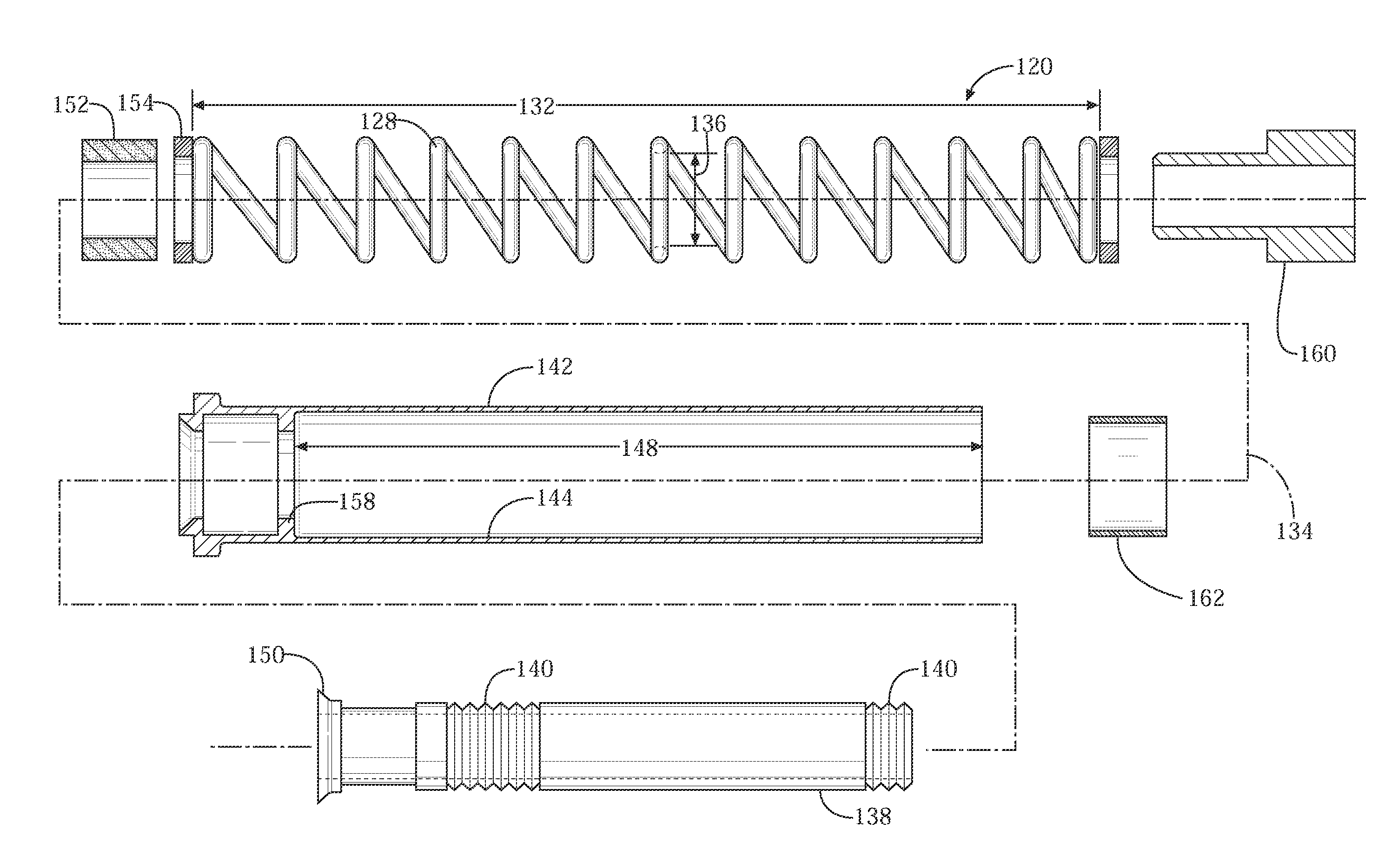
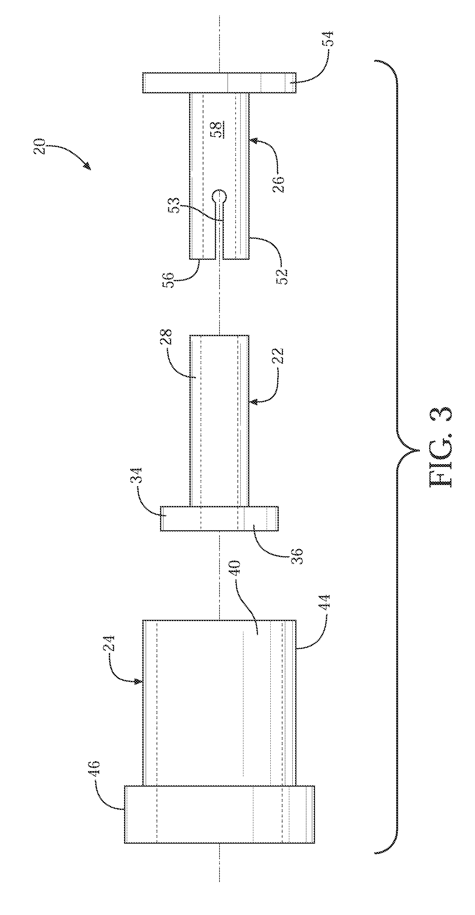
[0012]A charging assembly for an air gun is disclosed. The charging assembly includes a compression tube, and a piston having a head slideably disposed within the compression tube. The piston includes a skirt, which extends from the head. The piston is configured for movement from a rearward position to a forward position to compress a gas within the compression tube. The charging assembly further includes a power spring. The power spring includes a forward end and a rearward end. The forward end is disposed adjacent the head of the piston. The power spring is configured for movement from a compressed position to an uncompressed position to move the piston from the rearward position into the forward position. The charging system further includes a dampening system. The dampening system reduces vibration of the power spring in response to the movement of the power spring from the compressed position into the uncompressed position. The dampening system includes a rear guide tube at least partially disposed within an inner diameter of the power spring. The dampening system further includes a sleeve. The sleeve defines a bore with the rearward end of the power spring disposed within the bore of the sleeve. The sleeve and the rear guide tube support at least a portion of the power spring therebetween for reducing a length of the power spring free to oscillate to limit vibration of the power spring.
[0013]In another aspect of the invention, a power spring assembly for moving a piston within a compression tube of an air gun is disclosed. The power spring assembly includes a power spring, which extends along a longitudinal axis and defines a hollow core. The power spring is moveable from a compressed position into an uncompressed position when fired. The power spring assembly further includes a dampening system. The dampening system includes a rear guide tube at least partially disposed within the hollow core of the power spring. The rear guide tube is stationary relative to the movement of the power spring. The dampening system further includes a sleeve. The sleeve defines a bore, and is coupled to the rear guide tube. The rear guide tube is disposed within the bore, and cooperates with the sleeve to define an annular gap between the rear guide tube and the sleeve. The sleeve is positionally fixed relative to the rear guide tube, and is stationary with the rear guide tube relative to the movement of the power spring. A rearward end of the power spring is disposed within the annular gap. The rear guide tube and the sleeve cooperate to radially support a portion of the power spring to limit radial movement of the power spring along the portion to reduce vibration of the power spring when moved from the compressed position into the uncompressed position.
[0014]In another aspect of the invention, a dampening system for reducing vibration in a power spring of an air gun is disclosed. The dampening system includes a rear guide tube configured for radially supporting an inner diameter of the power spring. The dampening system further includes a sleeve defining a bore and coupled to and at least partially surrounding the rear guide tube. The rear guide tube is disposed within the bore. The sleeve is configured for radially constraining an outer diameter of the power spring. The sleeve and the rear guide tube are configured for supporting at least a portion of the power spring therebetween for reducing a length of the power spring that is free to oscillate to limit vibration of the power spring when fired.
[0015]Accordingly, the dampening system disclosed encapsulates a portion of the power spring between the rear guide tube and the sleeve to radially support the power spring when fired. Radially supporting the power spring stiffens the resistance of the power spring to oscillate, thereby reducing oscillation and / or vibration in the power spring when fired.

Problems solved by technology

These spring-powered air guns suffer from inaccuracy due to the hysteresis, vibration, and other harmonics resulting from the rapid unloading, decompression, or uncoiling of the power spring when fired.
While these prior art techniques for increasing air gun performance may achieve effective results for their intended purpose, they require significant modification to the air gun components and / or the replacement of most, if not the entire, charging system.
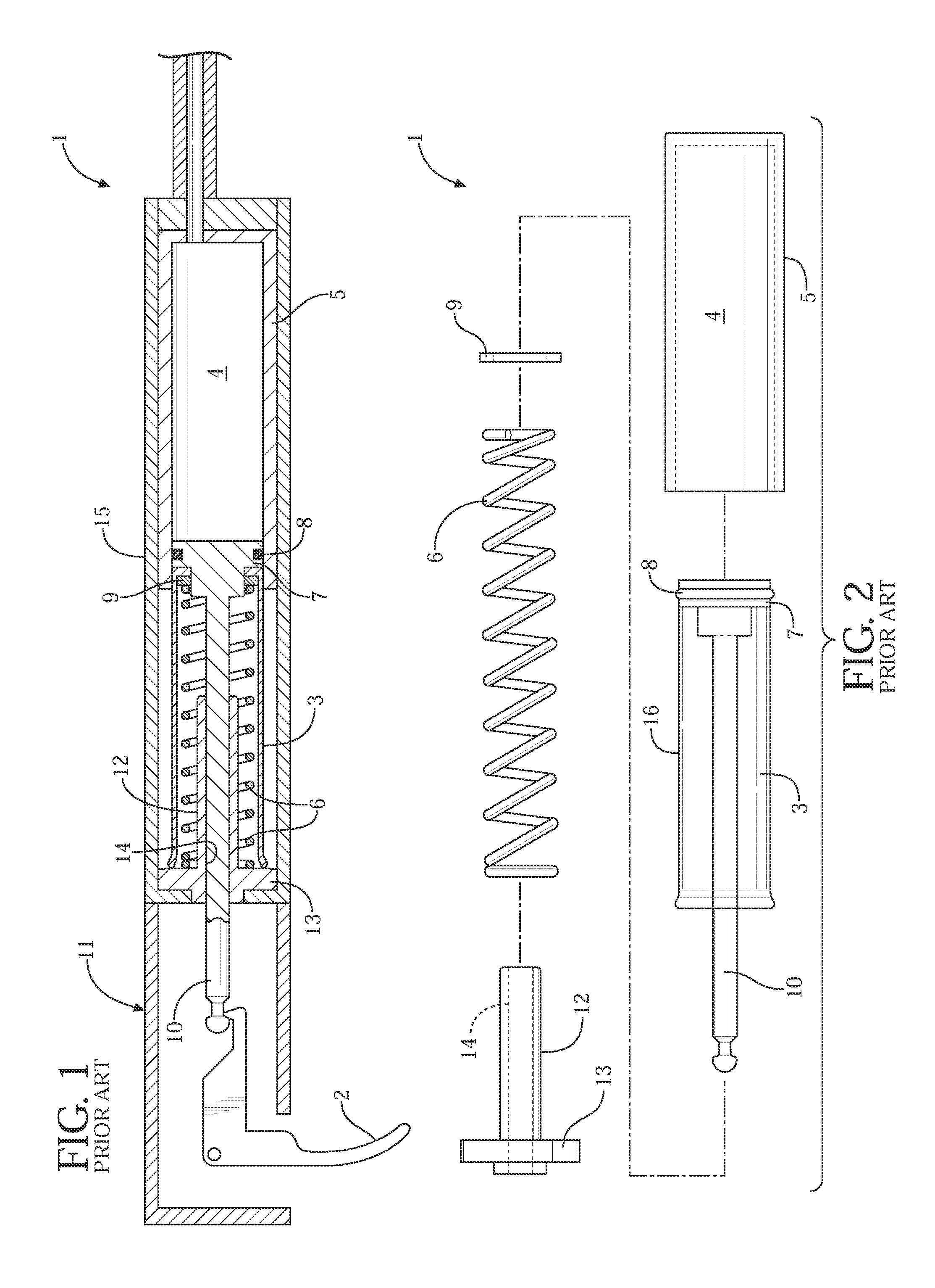
One disadvantage of current air guns is that this radial expansion and contraction of the power spring 6 during use necessitates that there is clearance between the inner wall of the skirt 16 of the piston 3 and the unloaded power spring 6.
This clearance, however, allows forward movement and uncoiling of the power spring 6 during firing, which produces vibration both during and immediately after firing has occurred and the piston has come to a rapid stop.
This vibration or oscillation of the power spring 6, both during and immediately after firing, both reduce the power supplied by the power spring 6 and reduce accuracy of the air gun.

Method used


Image

  • Air gun vibration dampener and method
  • Air gun vibration dampener and method
  • Air gun vibration dampener and method

Examples


Embodiment Construction

[0030]Referring to FIG. 3, an air gun dampening system is shown generally at 20. The dampening system 20 includes a rear guide tube 22, a sleeve 24 and a forward guide tube 26. The dampening system 20 reduces vibration in a coil spring charging assembly shown generally at 1 in FIGS. 4 and 6.

[0031]Referring also to FIGS. 4 -6, the charging system 1 is shown disposed within a receiving tube 15 of an air gun, and includes a compression tube 5 and a piston 3 at least partially disposed within the compression tube 5. The piston 3 includes a head 7 and a skirt 16, which extends from the head 7. The piston 3 is configured for movement from a rearward position to a forward position when the air gun is fired to compress a gas, such as air, within a chamber 4 of the compression tube 5.

[0032]The charging system 1 further includes a power spring 6. The power spring 6 includes a coil spring having a forward end and a rearward end. The forward end is disposed adjacent the head 7 of the piston 3, ...


PUM


Abstract

A vibration dampening system for an air gun charging system includes a rear guide tube and a forward guide tube that are received within opposite ends of an air gun power spring, and a sleeve that fits concentrically over the power spring. The rear guide tube and the sleeve cooperate to reduce the free length of the power spring allowed to vibrate, which reduces vibration and improves firing performance.

Description

CROSS-REFERENCE TO RELATED APPLICATIONS[0001]This application is a Continuation In part of U.S. patent Ser. No. 11 / 770,100, filed on Jun. 6, 2007, which claims the benefit if U.S. Provisional Patent Application Ser. No. 60 / 807,859, filed Jul. 20, 2006, the disclosure of which is hereby incorporated by reference.TECHNICAL FIELD[0002]The invention generally relates to air guns, and more particularly relates to a dampening system for reducing vibration in a charging assembly of an air gun.BACKGROUND OF THE INVENTION[0003]Although there are several types of systems for powering air guns, most air guns are powered by a power spring, e.g., a coil spring. The power spring actuates a hollow piston that covers or “skirts” the power spring. The piston includes a sear that engages a latch that is connected to a trigger assembly of the air gun.[0004]Generally, in air guns that incorporate a contained power spring energy source, cocking the power spring, i.e., compressing the power spring create...

Claims


Application Information

Patent Timeline
IPC IPC(8): F41B11/00
CPCF41B11/642
Inventor GORE, THOMAS
Owner THOMAS GORE LIVING TRUST
Learn More