Power seat driving apparatus for vehicle

a driving apparatus and seat technology, applied in the direction of movable seats, transportation and packaging, gearing, etc., can solve the problems of clashing damage, large stress and damage, and generation of stress, and achieve the effect of reducing rigidity and increasing tooth thickness

Inactive Publication Date: 2010-03-11
AISIN SEIKI KK
View PDF13 Cites 19 Cited by
  • Summary
  • Abstract
  • Description
  • Claims
  • Application Information

AI Technical Summary

Problems solved by technology

On the other hand, when a rotational speed is reduced, a gear may idly rotate for an amount corresponding to a backlash because of inertia, and tooth surfaces of gears may clash with each other, thereby causing generation of stress.
Furthermore, when the rotation stops, clashing damage may be generated.
Extensive stress and damage may occur specifically in a mechanism in which a deceleration rate is large.
According to the planetary gear mechanism disclosed in JP2005-344757A, although the backlash may be reduced, other drawbacks may exist, such that the number of components is increased, a size of the mechanism is enlarged, and a cost is increased.
On the other hand, when a general gear set is used for deceleration, it may be difficult to reduce the backlash and to improve the stability because torque outputted from the gear set becomes large.

Method used


Image

  • Power seat driving apparatus for vehicle
  • Power seat driving apparatus for vehicle
  • Power seat driving apparatus for vehicle

Examples


first embodiment

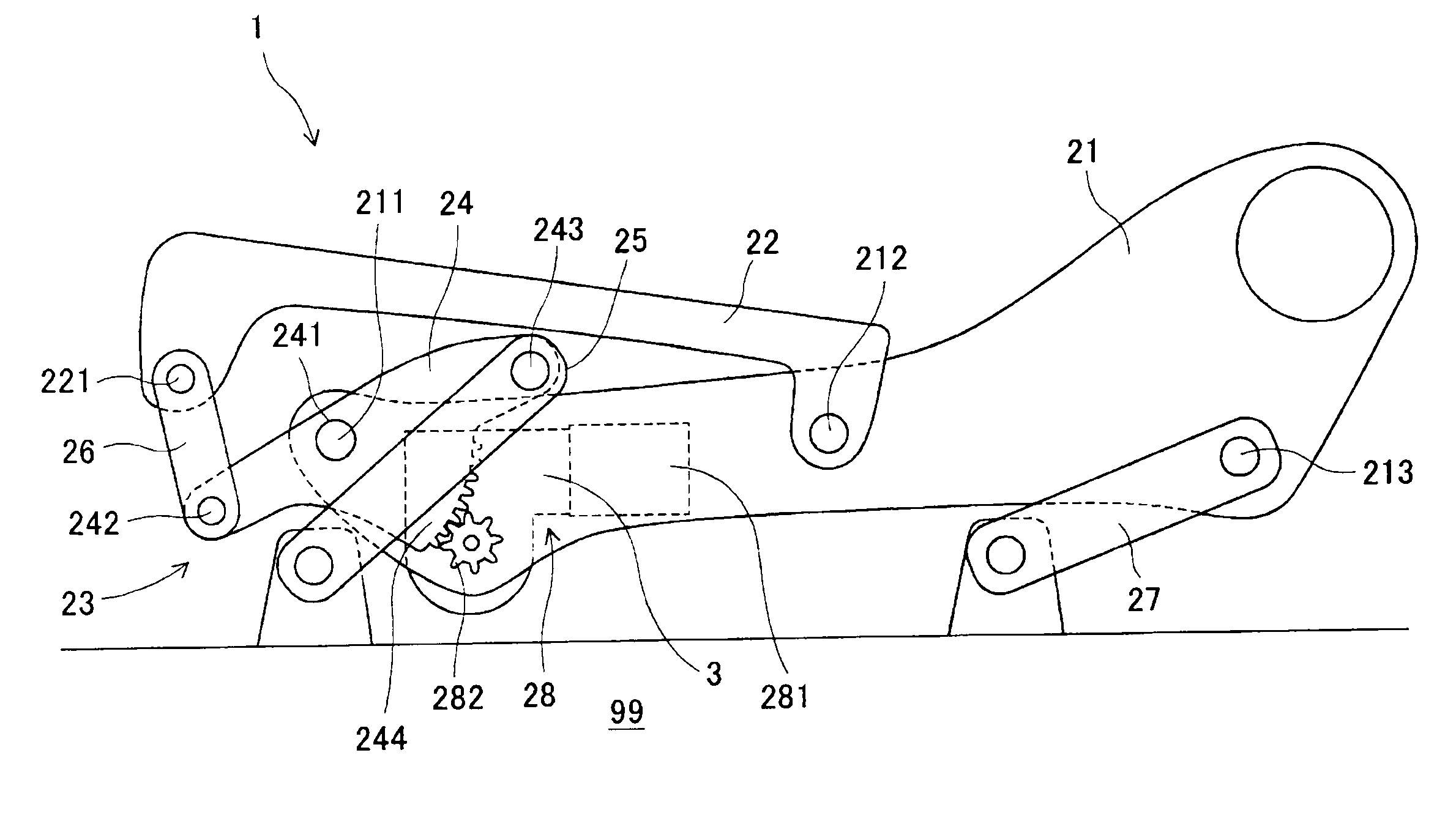
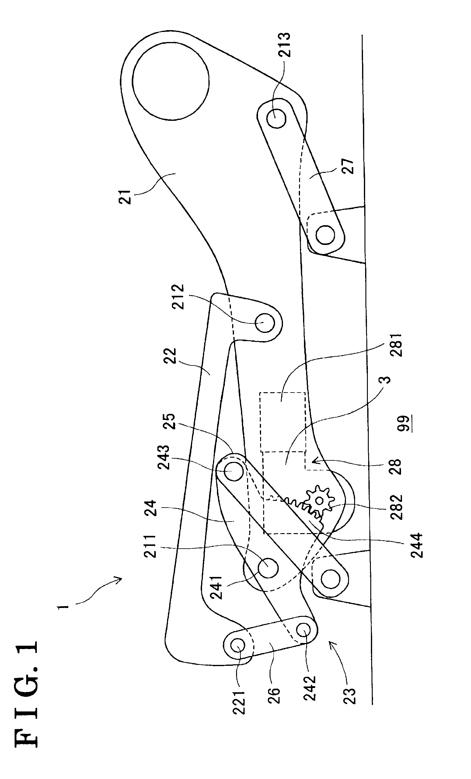
[0018]A first embodiment of a power seat driving apparatus 1 for a vehicle will be provided hereinafter with reference FIGS. 1 to 4. The power seat driving apparatus 1 includes left and right side brackets 21 holding a seat cushion at left and right side surfaces of the seat cushion, a cushion frame 22 holding the seat cushion at a bottom side of the seat cushion, left and right front pivot-link mechanisms 23 rotating in order to operate front portions of the side brackets 21 and the cushion frame 22 so as to pivot, left and right rear pivot links 27 rotating in order to operate rear portions of the side frames 21 so as to pivot, a front driving device 28 and a rear driving device. The power seat driving apparatus 1 includes substantially the same structures and functions at left and right sides thereof. Therefore, only one side of the power seat driving apparatus 1 will be described hereinafter, unless otherwise indicated.

[0019]A rear portion of the cushion frame 22 is supported by...

second embodiment

[0032]A second embodiment of the power seat driving apparatus 1 will be described hereinafter with reference to FIGS. 5 and 6. According to the second embodiment, a backlash of a second deceleration portion 50 (a deceleration mechanism) in an axial direction thereof and in a radial direction thereof is reduced. An elastic gear 54 of the second deceleration portion 50, which is different from the first embodiment, will be described mainly hereinafter. In FIG. 6, the output gear member 57 and the housing 61 are illustrated by dashed line.

[0033]The elastic gear 54 according to the second embodiment is made of resin material and is formed into a substantially annular shape. The elastic gear 53 includes elasticity and lower rigidity than the spur gear 52. The elastic gear 54 includes a third gear portion 541, a third shaft hole 542 and connection protruding portions 543. The third gear portion 531 includes a spur gear formed at an outer circumferential surface thereof. The third shaft ho...

third embodiment

[0037]A third embodiment of the power seat driving apparatus 1 will be described hereinafter with reference to FIGS. 7 and 8. According to the third embodiment, a rotational range of the output gear 282 is restricted. Only portions different from the first embodiment will be described mainly hereinafter. Configurations of the housing 6 of a decelerating portion 300 according to the third embodiment and the first deceleration portion 4 are similar to that of the first embodiment.

[0038]A second deceleration portion 7 (a deceleration mechanism) according to the third embodiment includes a pinion gear (a driving gear) 71, a spur gear (a driven gear) 72, and an elastic gear (a supplemental gear) 73. The second deceleration portion 7 further includes a stopper pin 74 and a stopper plate 75. The pinion gear 71, which is a driving portion of the second declaration portion 7, is coaxially integrally formed at an upper end of the helical gear 42 of the first deceleration portion 4. The pinion...


PUM


Abstract

A power seat driving apparatus for a vehicle includes a moving unit and a decelerating mechanism. The deceleration mechanism includes a driving gear, a driven gear engaging with the driving gear and driven to rotate while decelerating a rotational speed of the driving gear, a supplemental gear coaxially connected to the driven gear in an interlocking manner, made of a resin material having elasticity and lower rigidity than the driven gear, having a larger tooth thickness than a tooth thickness of the driven gear by an amount corresponding to a backlash, and engaging the driving gear together with the driven gear, and a housing accommodating and rotatably supporting the driving gear, the driven gear and the supplemental gear.

Description

CROSS REFERENCE TO RELATED APPLICATIONS[0001]This application is based on and claims priority under 35 U.S.C. §119 to Japanese Patent Application 2008-232828 filed on Sep. 11, 2008, the entire contents of which is incorporated herein by reference.FIELD OF THE INVENTION[0002]The present invention relates to a power seat driving apparatus for a vehicle having a decelerating mechanism for decelerating a driving force of a power supply and transmitting the decelerated driving force to a moving unit of a seat.BACKGROUND[0003]A seat apparatus for a vehicle is known, in which a motor, serving as a power supply, and a decelerating mechanism for decelerating a driving force of the motor and transmitting the decelerated driving force to a moving unit of a seat, are combined and operated in order to adjust an inclination of a front portion of a seat cushion of a seat for a vehicle in an upper-lower direction of the seat and in order to slidably adjust an entire seat in a front-rear direction o...

Claims


Application Information

Patent Timeline
Patent Type & Authority Applications(United States)
IPC IPC(8): B60N2/04B60N2/90
CPCB60N2/0232B60N2/1803B60N2205/20B60N2/1864B60N2/181B60N2/1615B60N2/165F16H1/16H02K7/1166F16H37/041F16H2055/185F16H55/18B60N2/02246
Inventor KOGA, YOSHITAKASUZUMURA, HIROKAZUTSUJI, EIICHIRO
Owner AISIN SEIKI KK
Why Eureka
Try Eureka