Electrical switching apparatus including a trip coil open circuit test circuit and system including the same
- Summary
- Abstract
- Description
- Claims
- Application Information
AI Technical Summary
Problems solved by technology
Method used
Image
Examples
example 1
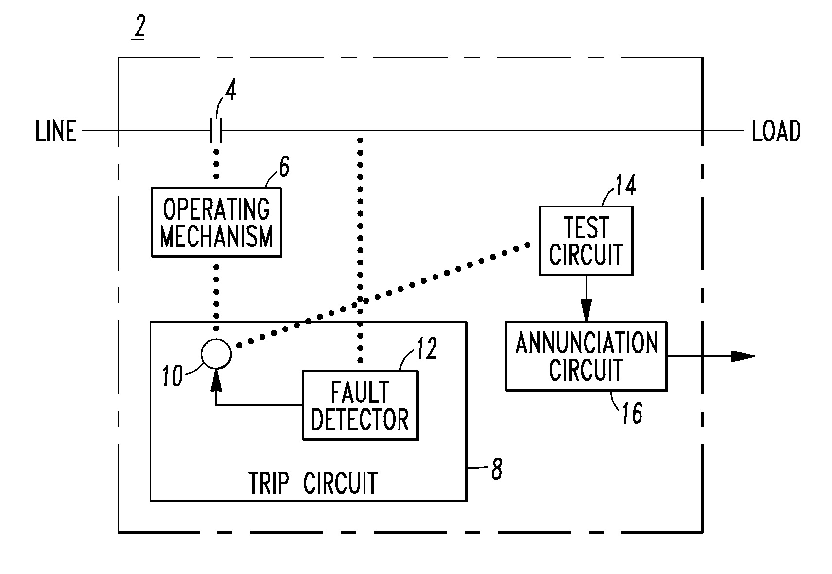
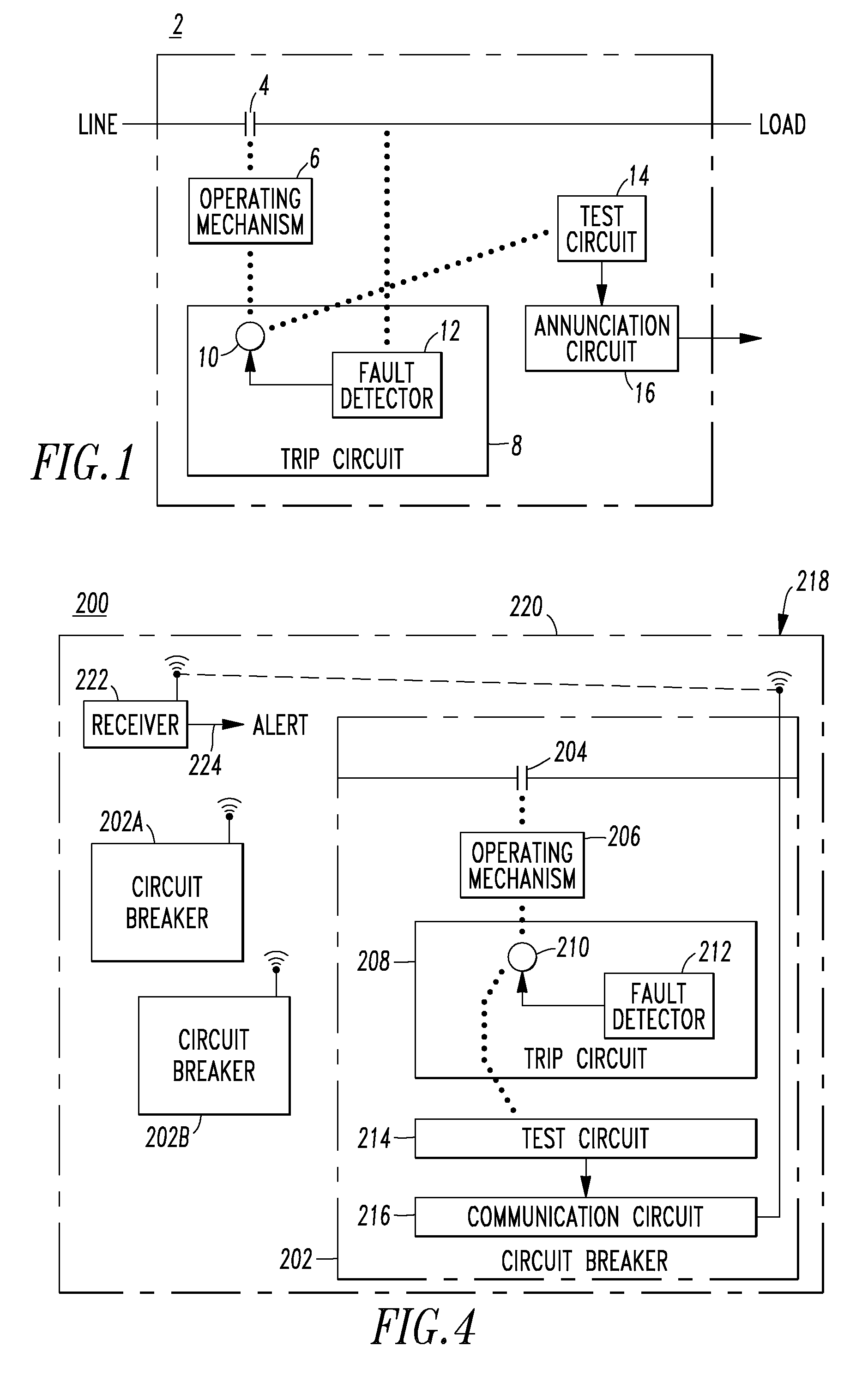
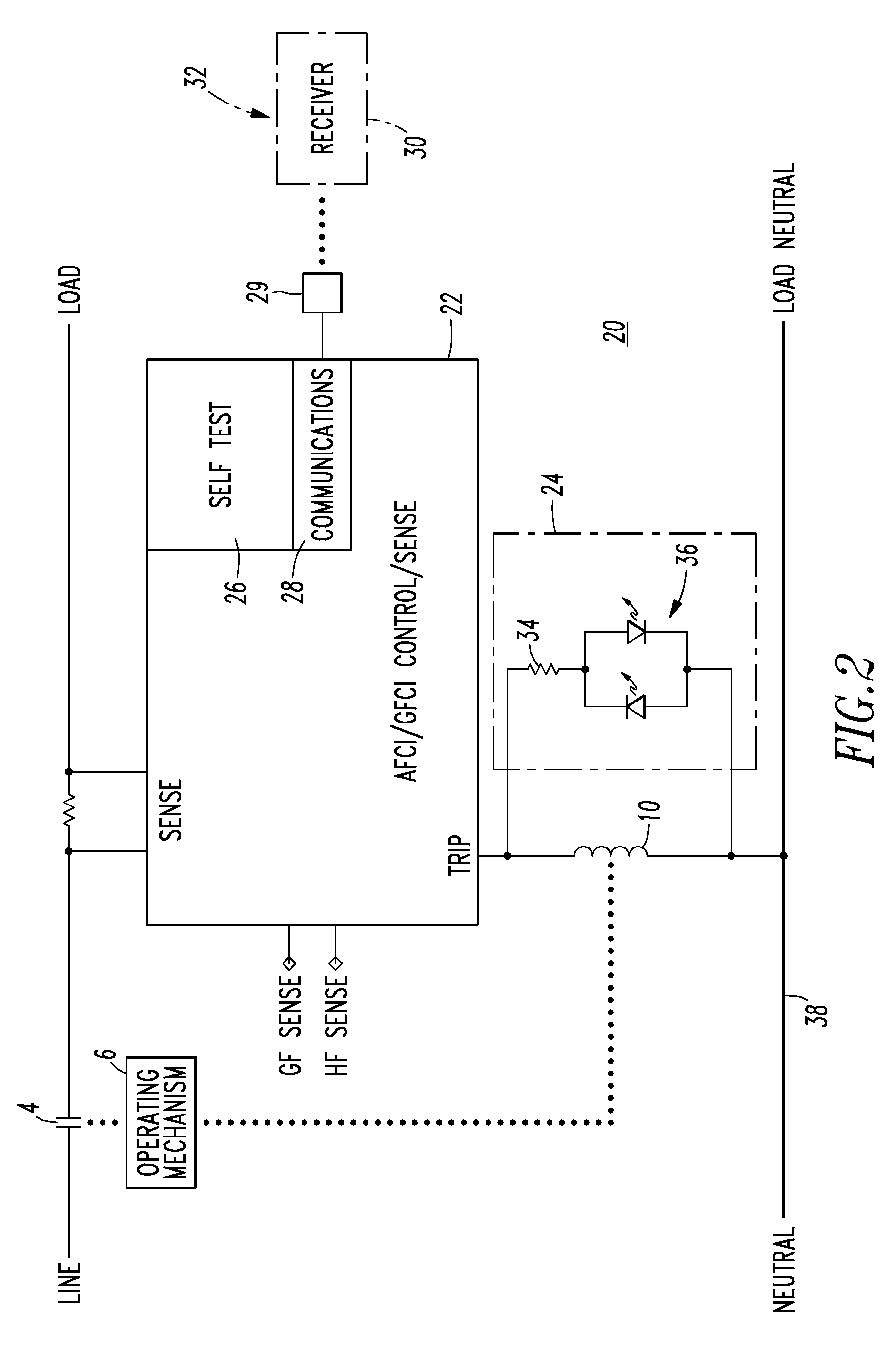
[0030]FIG. 2 shows an arc fault / ground fault circuit breaker 20 including the separable contacts 4, the operating mechanism 6 and the trip coil 10 of FIG. 1, along with an AFCI / GFCI control / sense circuit 22, an open coil sense and indication circuit 24, a self test circuit 26 and a communications circuit 28. It will be appreciated that these circuits 22,24,26,28 can be combined and / or can be implemented by any suitable number of analog, digital and / or processor-based circuits. The example circuits 22,24,26,28 cooperatively detect and communicate circuit breaker failure states to a receiver 30 (shown in phantom line drawing) in, at, on or near an electrical distribution panel 32 (shown in phantom line drawing). One or both of the open coil sense and indication circuit 24 and the self test circuit 26 detect a failure of the trip coil 10. One or both of the open coil sense and indication circuit 24 and the communications circuit 28 provide a corresponding annunciation of this failure c...
example 2
[0031]In this example, the trip coil 10 includes a voltage. One or both of the open coil sense and indication circuit 24 and the self test circuit 26 can be a test circuit structured to sense the voltage of the trip coil 10, determine if that voltage is greater than a predetermined value, and responsively determine an open circuit condition of the trip coil 10.
[0032]The circuit 24, as shown, includes the series combination of a resistor 34 and a bi-directional light emitting diode (LED) 36 (i.e., the LED is illuminated by current flowing in either direction through the resistor 34). As will be described, during the open circuit condition of the trip coil 10, a predetermined current flows through that series combination. In the absence of that open circuit condition, the voltage of the trip coil 10 is insufficient to illuminate the bi-directional LED 36.
[0033]The detection of the open trip coil 10 of the circuit breaker 20 is possible since the operating power for the AFCI / GFCI contr...
example 3
[0035]For example and without limitation, the resistance of the trip coil 10 is normally about 20 ohms and with the nominal current through the AFCI / GFCI control / sense circuit 22 of about 12 mA, the voltage across the trip coil 10 is, thus, normally about 0.2 V. The example resistance of resistor 34 is about 5 kΩ (with a 3 W power rating to make this circuit highly reliable) and the voltage thereacross is, thus, about 50 V when the trip coil 10 is open. If the trip coil 10 is open, then the current through resistor 34 provides the power to operate the circuit 22 and, also, lights the LED 36 to visually indicate the trip coil failure. Hence, the open coil status sensor provided by the circuit 24 can preferably be sized to provide an alternate path in order to keep the electronics of the AFCI / GFCI control / sense circuit 22 operational and / or to illuminate the LED 36 for failure indication.
PUM
 Abstract
Description
Claims
Application Information
 - R&D
- Intellectual Property
- Life Sciences
- Materials
- Tech Scout
- Unparalleled Data Quality
- Higher Quality Content
- 60% Fewer Hallucinations
Browse by: Latest US Patents, China's latest patents, Technical Efficacy Thesaurus, Application Domain, Technology Topic, Popular Technical Reports.
© 2025 PatSnap. All rights reserved.Legal|Privacy policy|Modern Slavery Act Transparency Statement|Sitemap|About US| Contact US: help@patsnap.com


