LED lamp driving power test method

A technology for driving power supply and LED lights, applied in the direction of power supply testing, etc., can solve problems such as poor contact between LED lights and solder joints, LED lights soldering, open load, etc., and achieve the effect of reducing after-sales service costs.

Active Publication Date: 2014-10-29
SHENZHEN OCEANS KING LIGHTING ENG CO LTD +1
View PDF7 Cites 5 Cited by
  • Summary
  • Abstract
  • Description
  • Claims
  • Application Information

AI Technical Summary

Problems solved by technology

Because the power of a single LED is generally small, high-power LED lights require multiple LEDs to work in series. Since LED lights are usually welded on printed boards, LED lights may have virtual soldering, or LED lights may be damaged due to vibration, temperature changes, etc. Poor contact with the solder joints. In these cases, the LED drive power supply will have an open circuit load, resulting in damage to the LED drive power supply.

Method used


Image

  • LED lamp driving power test method

Examples


Embodiment Construction

[0036] The following will clearly and completely describe the technical solutions in the embodiments of the present invention with reference to the accompanying drawings in the embodiments of the present invention. Obviously, the described embodiments are only some, not all, embodiments of the present invention. Based on the embodiments of the present invention, all other embodiments obtained by persons of ordinary skill in the art without creative efforts fall within the protection scope of the present invention.

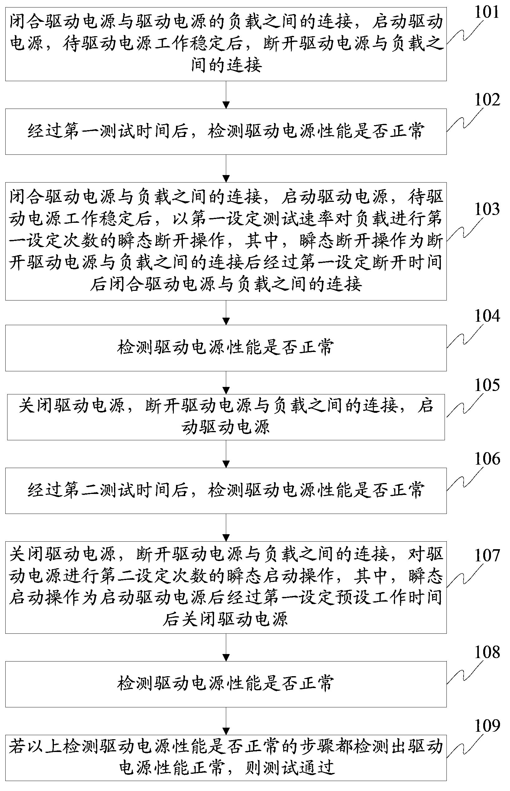
[0037] Please refer to figure 1 , figure 1 It is a flowchart of a method for testing LED lamp driving power provided by an embodiment of the present invention, including:

[0038] 101. Close the connection between the driving power supply and the load of the driving power supply, start the driving power supply, and disconnect the connection between the driving power supply and the load after the driving power supply works stably.

[0039] Step 101 simulates the s...


PUM


Abstract

An embodiment of the invention discloses an LED lamp driving power test method. The LED lamp driving power test method comprises the steps of simulating various open circuit states of an LED driving power; conducting an open circuit test on the LED driving power; and passing the test if the performance of the driving power is detected to be normal under the various open circuit states. According to the invention, the LED lamp driving power test method can be used for testing whether the open states of the LED lamp driving power would result in damage to the driving power at before an LED lamp leaves the factory, unqualified LED lamps can be prevented from entering the market, and the after-sales service cost is reduced.

Description

technical field [0001] The invention relates to the field of circuit testing, in particular to a testing method for an LED lamp driving power supply. Background technique [0002] Light Emitting Diodes (LEDs) have been widely used in recent years due to their advantages of long life, high luminous efficiency, low radiation, and low power consumption. LED lights are widely used in roads, tunnels, factories, shopping malls, residential areas and so on. [0003] The LED lamp includes a driving power supply and an LED, and the LED is a load of the driving power supply. Because the power of a single LED is generally small, high-power LED lights require multiple LEDs to work in series. Since LED lights are usually welded on printed boards, LED lights may have false soldering, or LED lights may be damaged due to vibration, temperature changes, etc. Poor contact with the solder joints, in these cases, the LED drive power will have a load open circuit, resulting in damage to the LE...

Claims


Application Information

Patent Timeline
Patent Type & Authority Applications(China)
IPC IPC(8): G01R31/40
Inventor 周明杰杜勇强
Owner SHENZHEN OCEANS KING LIGHTING ENG CO LTD
Why Eureka
Try Eureka