Packet transfer control method, mobile terminal and home agent used in its method
- Summary
- Abstract
- Description
- Claims
- Application Information
AI Technical Summary
Benefits of technology
Problems solved by technology
Method used
Image

Examples
first embodiment
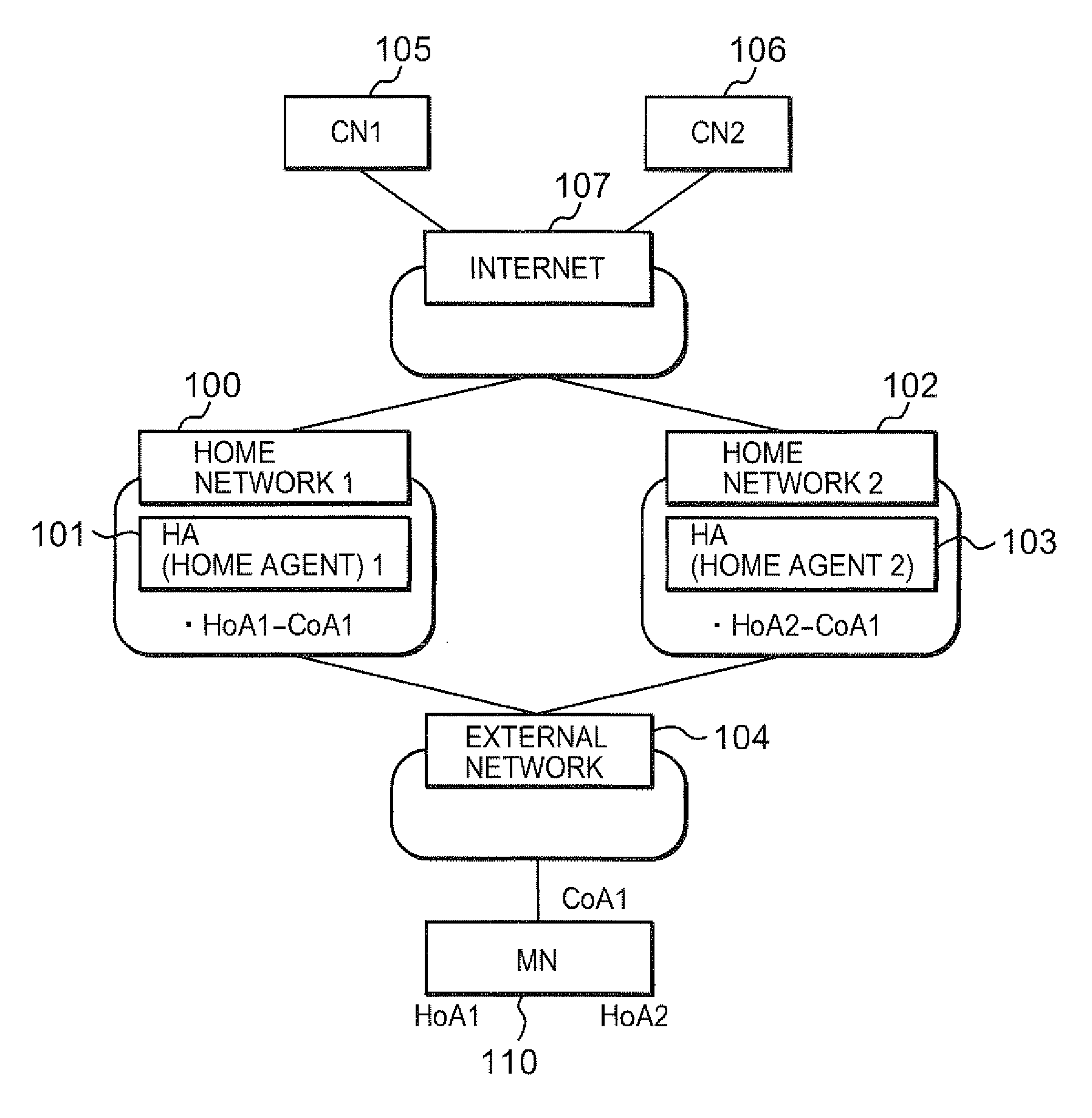
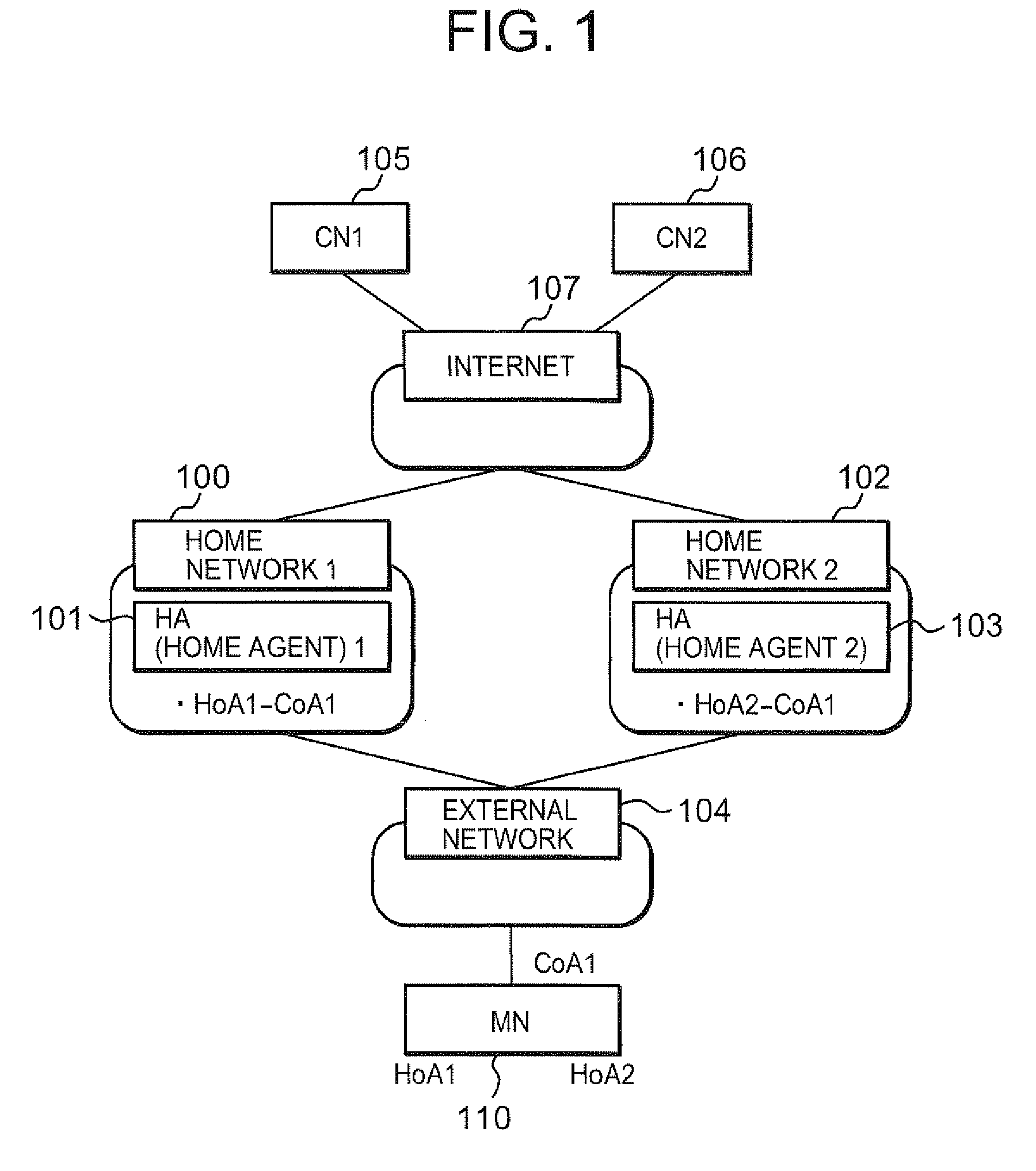
[0050]First, a network configuration according to a first embodiment of the present invention will be described with reference to FIG. 1. A HA 1 (101) present on a home network 1 (100) manages a HoA 1 of a MN 110. On the other hand, a HA 2 (103) present on a home network 2 (102) manages a HoA 2 of the MN 110. The MN 110 is connected to an external network 104 and holds a CoA 1 as an address to be used in the external network 104. A CN 1 (105) and a CN 2 (106) are correspondent nodes (communication terminals) of the MN 110 and are present on the internet 107.
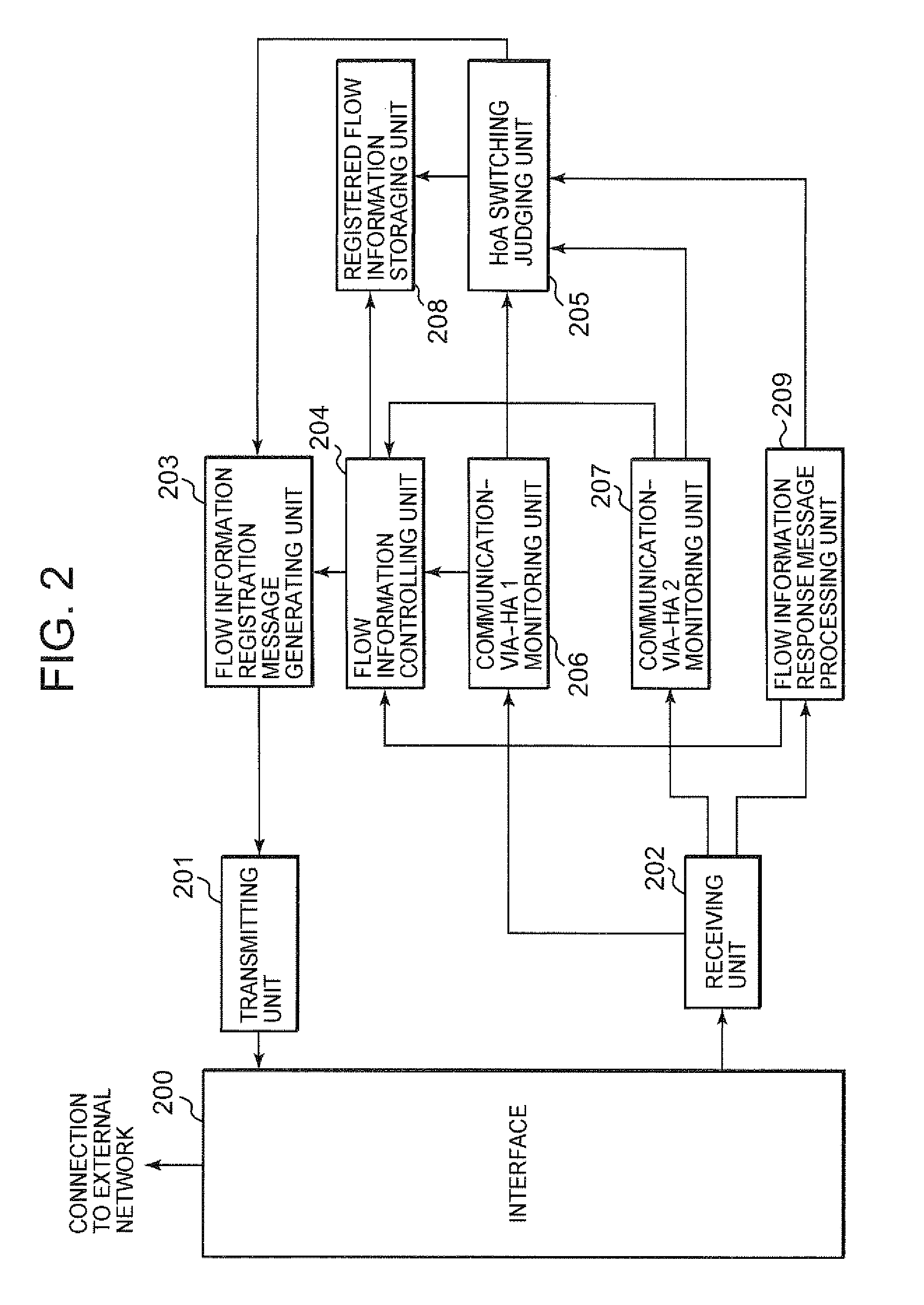
[0051]Next, a MN according to the first embodiment of the present invention will be described with reference to FIG. 2. The MN includes an interface 200, a transmitting unit 201, a receiving unit 202, a flow information registration message generating unit 203, a flow information controlling unit 204, a HoA switching judging unit 205, a communication-via-HA 1 monitoring unit 206, a communication-via-HA 2 monitoring unit 207, a re...
second embodiment
[0085]A second embodiment of the present invention will be described. A network configuration according to the second embodiment is similar to the network configuration according to the first embodiment shown in FIG. 1. Therefore, the second embodiment will be described with reference to FIG. 1 when required. First, a MN according to the second embodiment of the present invention will be described with reference to FIG. 9. The MN according to the second embodiment differs from the MN according to the first embodiment only regarding operations of a HoA switching judging unit 905 and a flow information registration message generating unit 903. Respective operations will be described below.
[0086]The HoA switching judging unit 905 receives information from a communication-via-HA 1 monitoring unit 906 and a communication-via-HA 2 monitoring unit 907. When the HoA switching judging unit 905 judges that a HoA being used in an arbitrary flow should be switched, the HoA switching judging uni...
third embodiment
[0118]A third embodiment of the present invention will be described. A network configuration according to the third embodiment is similar to the network configuration according to the first embodiment shown in FIG. 1. Therefore, the third embodiment will be described with reference to FIG. 1 when required. First, a MN according to the third embodiment of the present invention will be described. A configuration of the MN according to the third embodiment of the present invention is similar to the configuration of the MN according to the first embodiment shown in FIG. 2. Therefore, units having the same name are described using the same reference number. The MN according to the third embodiment differs from the MN according to the first embodiment only regarding operations of the HoA switching judging unit 205 and the flow information registration message generating unit 203. Respective operations will be described below.
[0119]The HoA switching judging unit 205 receives information fr...
PUM
 Abstract
Description
Claims
Application Information
 - R&D Engineer
- R&D Manager
- IP Professional
- Industry Leading Data Capabilities
- Powerful AI technology
- Patent DNA Extraction
Browse by: Latest US Patents, China's latest patents, Technical Efficacy Thesaurus, Application Domain, Technology Topic.
© 2024 PatSnap. All rights reserved.Legal|Privacy policy|Modern Slavery Act Transparency Statement|Sitemap