
Extrapolation system for solar access determination

Inactive Publication Date: 2010-03-11
MACDONALD WILLARD S +1
View PDF21 Cites 22 Cited by
  • Summary
  • Abstract
  • Description
  • Claims
  • Application Information

AI Technical Summary

Problems solved by technology

As a result, these measurement systems are not well suited for determining solar access at locations that are inaccessible or remote from the measurement systems, which may be a disadvantage in a variety of contexts.
However, due to space constraints, or in order to minimize shading by obstructions that reduce solar radiation exposure, installation sites of solar energy systems are typically relegated to rooftops or other remote locations.
Determining solar access at these installation sites relies on positioning a prior art solar access measurement system on the rooftop or other remote location, which may be a time-consuming, inconvenient, or unsafe task.
However, the prior art solar access measurement systems are unsuitable for determining solar access in the building's design phase when the installation sites are not yet accessible to accommodate positioning of the solar access measurement system.
However, prior art solar access measurement systems are also of little use in this context, where the locations of these building elements are typically not accessible for placement of the measurement systems.
However, this technique applies only to a location that has a vertical offset from where the solar access measurement system is positioned.
In addition, this technique relies on measuring the distance to the obstructions that cause the shading, which may be time-consuming or impractical, depending on the physical attributes of the terrain that contains the obstructions.

Method used


Image

  • Extrapolation system for solar access determination
  • Extrapolation system for solar access determination
  • Extrapolation system for solar access determination

Examples


Embodiment Construction

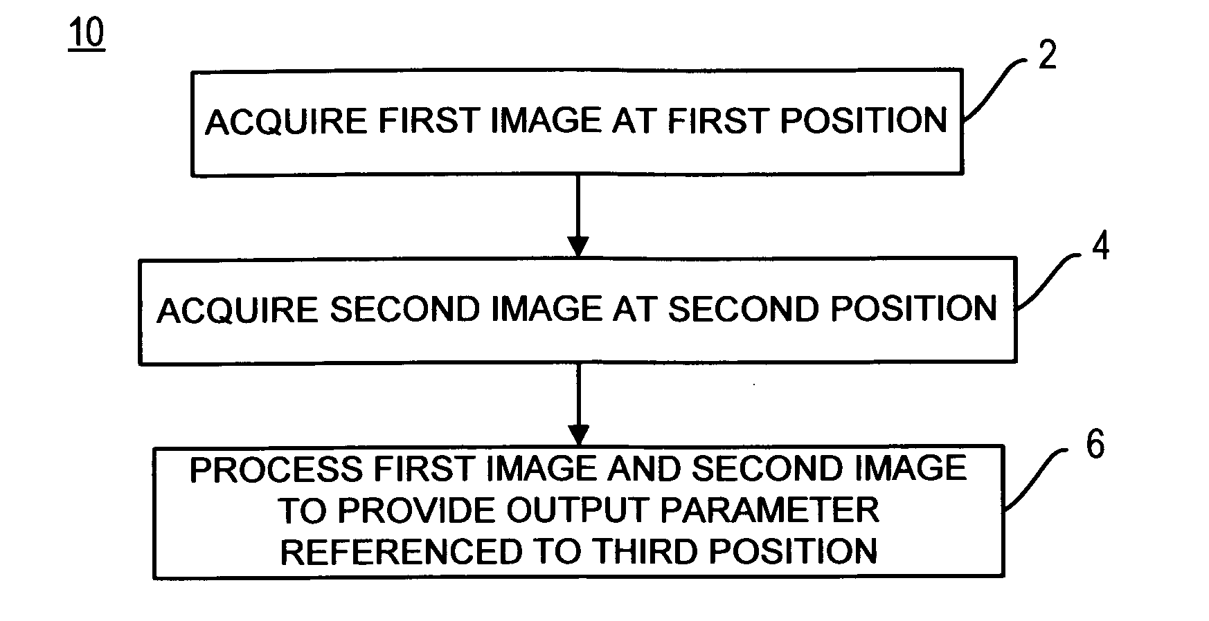
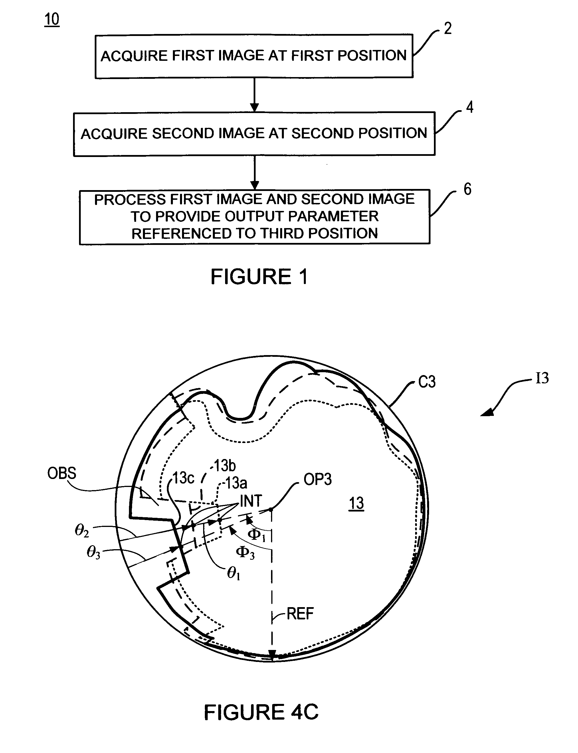
[0018]FIG. 1 shows a flow diagram of an extrapolation system 10 according to embodiments of the present invention. The extrapolation system 10 includes acquiring an orientation-referenced image (hereinafter “image I1”) at a first position P1 (step 2), acquiring an orientation referenced image (hereinafter “image I2”) at a second position P2 (step 4), and processing the image I1 acquired at the first position P1 and the image I2 acquired at the second position P2 to provide a detected skyline 13c, a set of azimuth and elevation angles Φ3, θ3, a determination of solar access 15, or other output parameter 11 (shown in FIG. 3) extrapolated to a third position P3 that is offset from the first position P1 and the second position P2 (step 6).

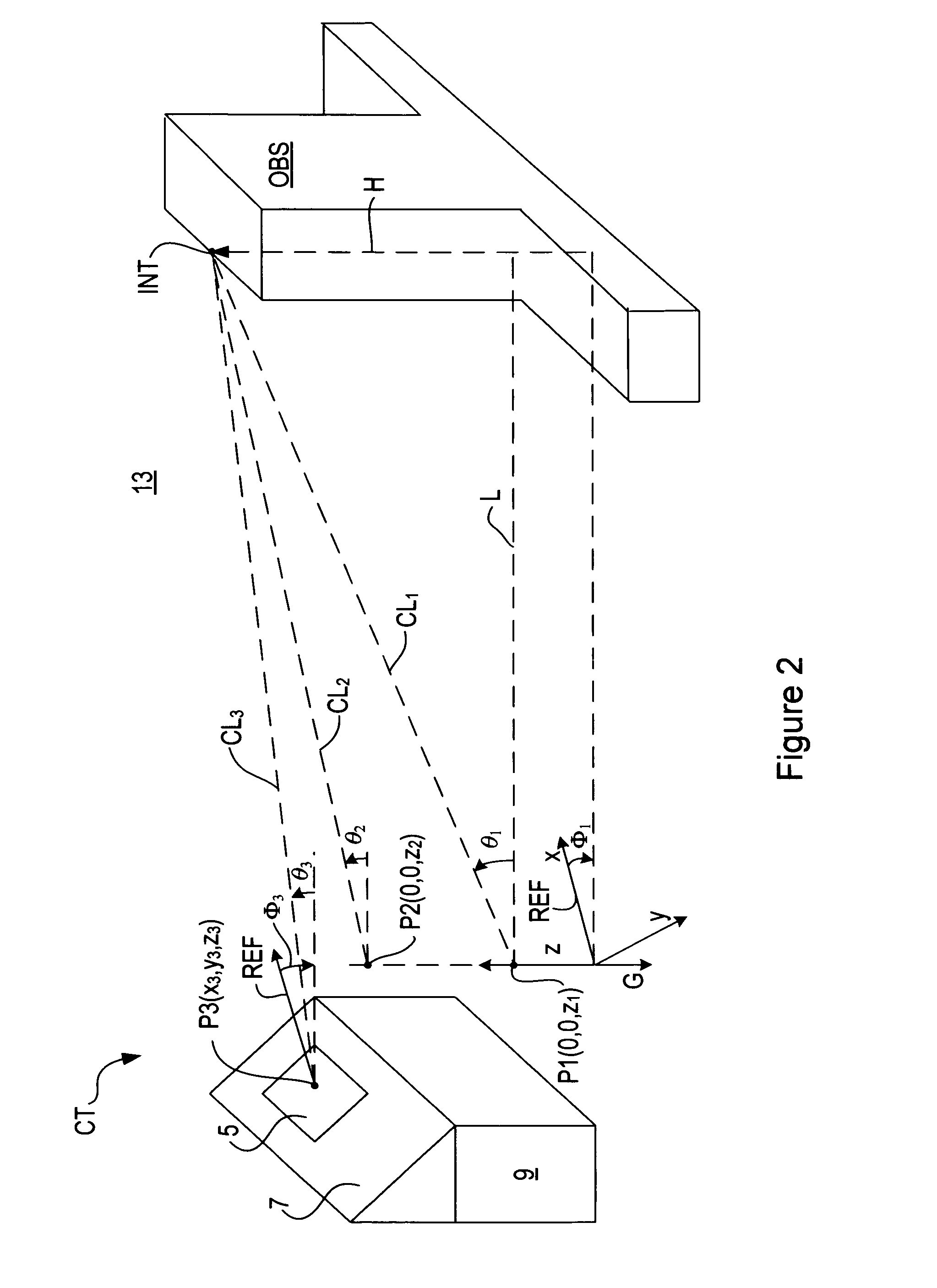
[0019]FIG. 2 shows an example physical context CT for application of the extrapolation system 10 according to embodiments of the present invention. In FIG. 2, the third position P3 is shown at a proposed installation site 5 for a solar energy system (n...


PUM


Abstract

An extrapolation system includes acquiring a first orientation-referenced image at a first position, acquiring a second orientation-referenced image at a second position having a vertical offset from the first position, and processing the first orientation-referenced image and the second orientation-referenced image to provide an output parameter extrapolated to a third position that has an offset from the first position and the second position.

Description

CROSS-REFERENCE TO RELATED APPLICATIONS[0001]N / A.BACKGROUND OF THE INVENTION[0002]Solar access refers to the characterization of solar radiation exposure at a designated location. Solar access accounts for daily and seasonal variations in solar radiation exposure that may result from changes in atmospheric clearness, shading by obstructions, or variations in incidence angles of the solar radiation due to the relative motion between the Sun and the Earth. Prior art measurement systems for characterizing solar access typically enable solar access to be determined only at the locations where the measurement systems are positioned. As a result, these measurement systems are not well suited for determining solar access at locations that are inaccessible or remote from the measurement systems, which may be a disadvantage in a variety of contexts.[0003]For example, determining solar access at an installation site of a solar energy system prior to installing the solar energy system may prov...

Claims


Application Information

Patent Timeline
IPC IPC(8): G06K9/64
CPCG06T3/00G01W1/12
Inventor MACDONALD, WILLARD S.GALLI, MARK B.
Owner MACDONALD WILLARD S
Learn More