Fixing control device, fixing device, and image forming apparatus
- Summary
- Abstract
- Description
- Claims
- Application Information
AI Technical Summary
Benefits of technology
Problems solved by technology
Method used
Image
Examples
fifth embodiment
[0082]Now, an exemplary circuit of a power supply is descried with reference to FIG. 9. As shown, a commercial power supply 200 supplies direct current power and heats a fixing heater HT1 via a reply 206 as a switching element, a rectifier 211, and a step-down circuit 207. On the other hand, a storage element 202 included in an auxiliary power supply 220 is supplied by the commercial power supply 200 with power and is charged. The storage element 202 then supplies the direct current power and heats the fixing heater HT1 via the step-down circuit 207.
[0083]In the auxiliary power supply 220, there is provided a charge / discharge control section 203 to control charging and discharging. As the storage element 202, an electric two-layer capacitor, a condenser, and a primary battery or the like are used. The charge / discharge control section 203 includes a charging device (e.g. included in the charge / discharge control section 203) that causes the storage element 202 to receive and be charg...
sixth embodiment
[0085]Now, a sixth embodiment is described, in which a secondary power supplying device is used during an initial phase when a heater is turned on. A storage capacity of the auxiliary power supply 220 is defined by the storage element 202. Specifically, if the storage amount is sufficiently large, the auxiliary power supply can always be used. However, when the storage capacity of the storage element 202 increases, the size increases, thereby parts become expensive. Thus, the parts are expected as small as possible. When a usage situation is limited, the auxiliary power supply is most efficiently used during an initial phase when a heater is turned on and a change of resistance is largest.
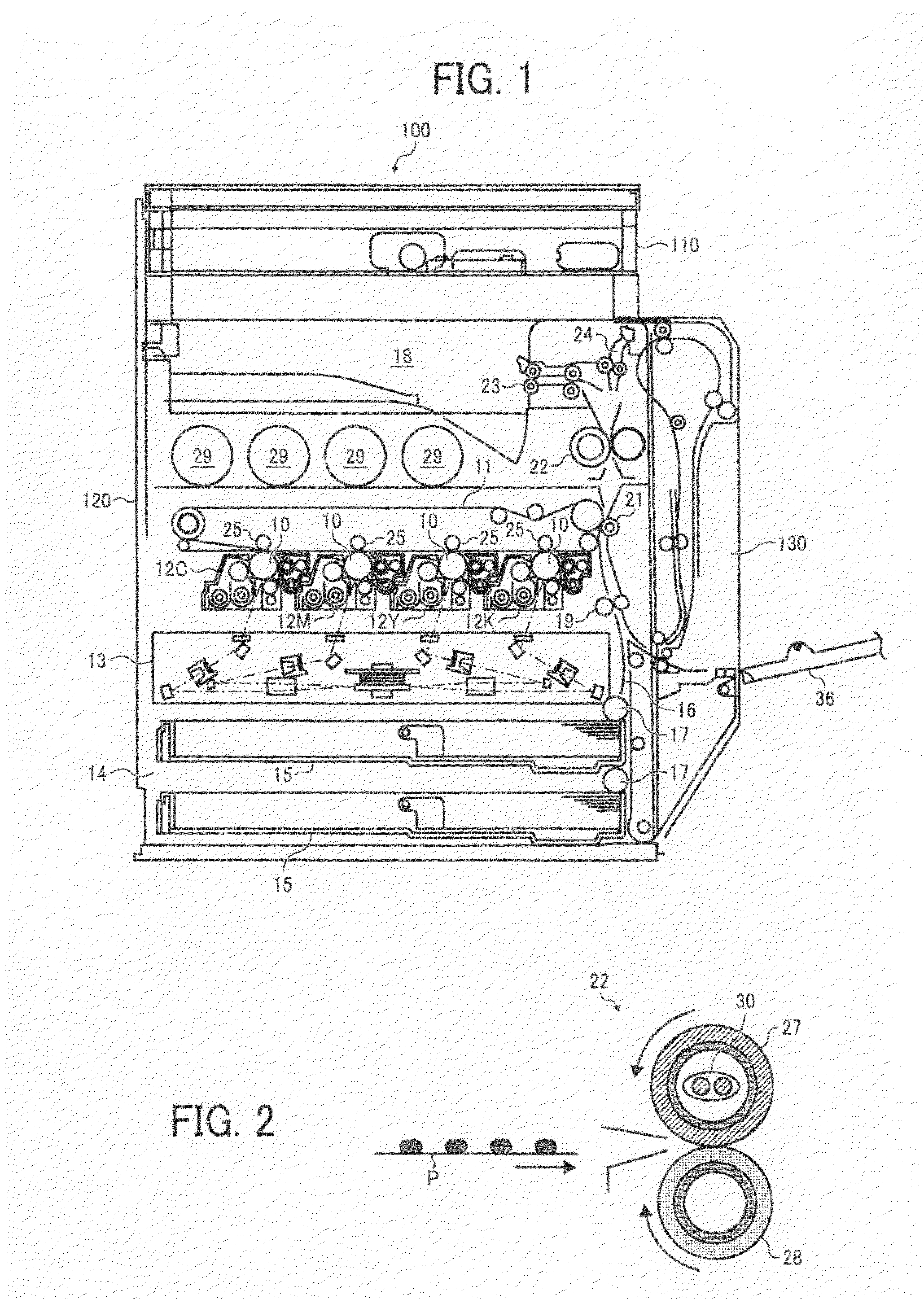
[0086]An exemplary configuration of fifth and sixth embodiments is now described with reference to FIG. 9. As shown, the fixing device 122 includes a fixing roller (a heating roller) 301 having a heater HT1, and a pressurizing roller having a heater HT2 pressure contacting the fixing roller 301. Th...
seventh embodiment
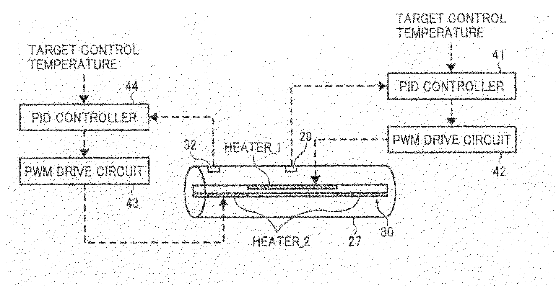
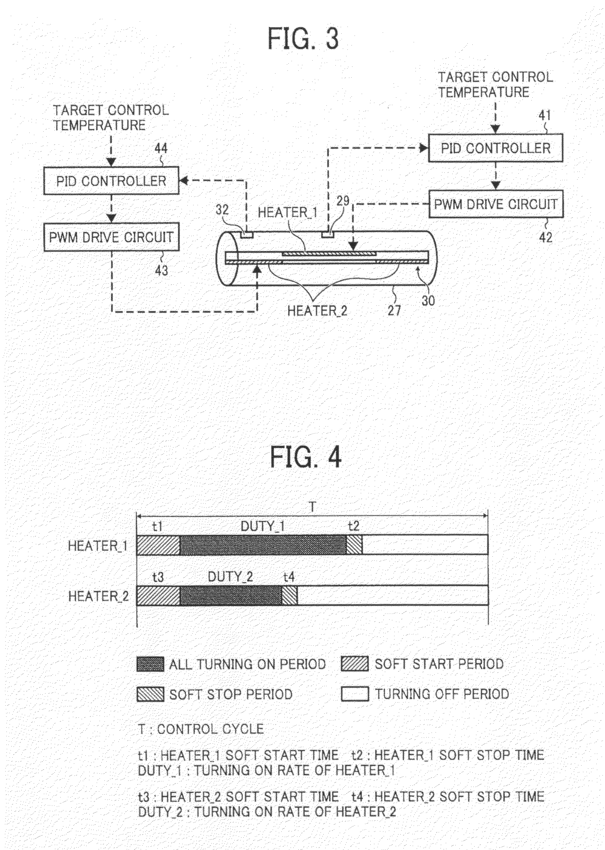
[0087]Now, a seventh embodiment is described, in which a heater is tuned on by a direct current power supply instead of the auxiliary power supply. Specifically, even not shown, the commercial power supply is converted into a direct current and a direct current power supply turns on each of the heaters (e.g. heaters 1 and 2 built in the fixing roller, or heaters HT1 and HT2 built in the respective fixing and pressurizing rollers). Since turning on the heater by means of the direct current power supply is hardly affected by a change of resistance, the soft start time period can be more effectively decreased than a turning on method using alternating current. Thus, a change of a voltage in the commercial power supply line and generation of a flicker phenomenon can be avoided.
[0088]In the above-mentioned various embodiments, the PID controller is used to calculate a power distribution time period (i.e. DUTY) for a heater. However, a similar controller, such as an I-PD controller, a PI-...
PUM
 Abstract
Description
Claims
Application Information
 - R&D
- Intellectual Property
- Life Sciences
- Materials
- Tech Scout
- Unparalleled Data Quality
- Higher Quality Content
- 60% Fewer Hallucinations
Browse by: Latest US Patents, China's latest patents, Technical Efficacy Thesaurus, Application Domain, Technology Topic, Popular Technical Reports.
© 2025 PatSnap. All rights reserved.Legal|Privacy policy|Modern Slavery Act Transparency Statement|Sitemap|About US| Contact US: help@patsnap.com


