Fuel cell system and air supply method thereof

a fuel cell and air supply technology, applied in the direction of fuel cells, fuel cell components, fuel cell groupings, etc., can solve the problems of non-economic cost, ignition and flame failure of the burner, etc., and achieve the effect of stably coping and efficient fuel cell system operation

Inactive Publication Date: 2010-03-11
SAMSUNG ELECTRONICS CO LTD
View PDF9 Cites 7 Cited by
  • Summary
  • Abstract
  • Description
  • Claims
  • Application Information

AI Technical Summary

Benefits of technology

The present invention provides an air supply device and control method for a fuel cell system that can automatically adjust for pressure loss and pulsation within the system. This allows for efficient and stable operation of the fuel cell system while using a minimum number of balance-of-plant units for air supply.

Problems solved by technology

The technical problem addressed in this patent text is the need for an economical and effective supply system for stack air and burner air in a fuel cell system, taking into consideration the influence of these gases on the production of high-quality hydrogen and the generation of electricity in the stack. The text describes the use of air pumps and blowers to supply these gases, but the cost of this method is not ideal. Therefore, the patent aims to provide a solution to this problem by developing a balance-of-plant (BOP) unit and control method for the supply of stack air and burner air.

Method used


Image

  • Fuel cell system and air supply method thereof
  • Fuel cell system and air supply method thereof
  • Fuel cell system and air supply method thereof

Examples


Embodiment Construction

[0049]Reference will now be made in detail to the embodiments of the present invention, examples of which are illustrated in the accompanying drawings. The embodiments are described below to explain the present invention by referring to the figures.

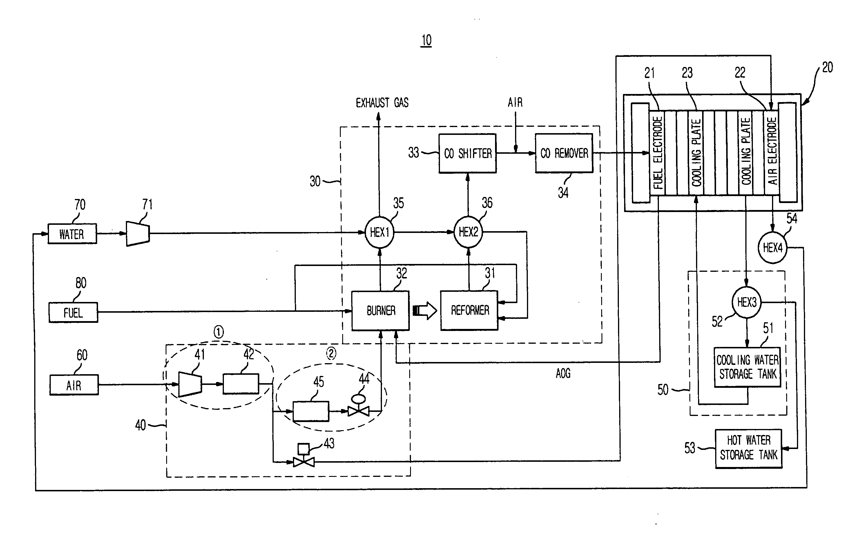
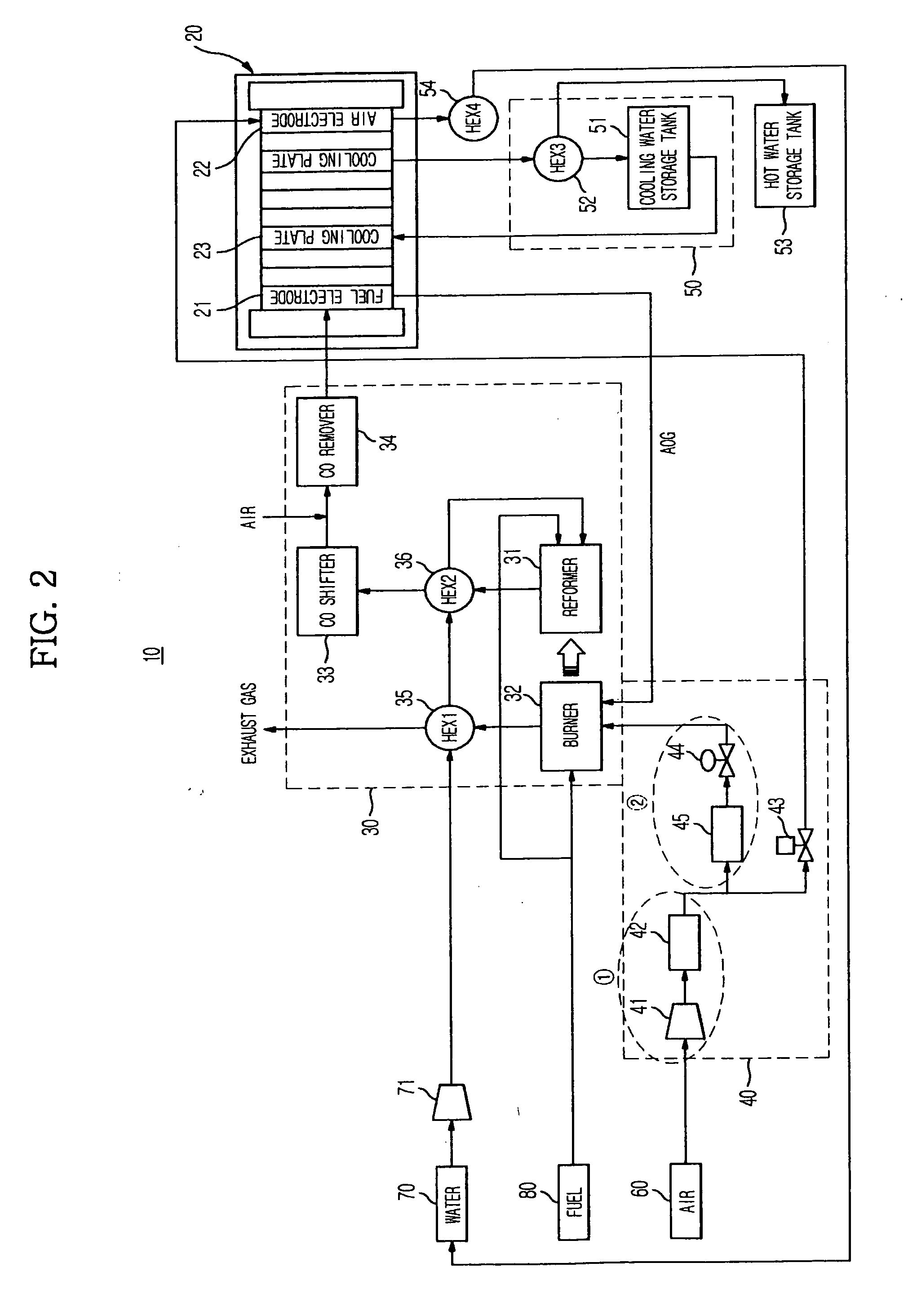
[0050]FIG. 2 is a block diagram illustrating a fuel cell system according to an embodiment of the present invention.

[0051]Referring to FIG. 2, the fuel cell system 10 according to the illustrated embodiment of the present invention includes a stack 20 to generate electricity, a fuel treating unit 30 to produce hydrogen to be supplied to the stack 20, an air supplying unit 40 to supply fuel 80 to the fuel treating unit 30, a cooling unit 50 to cool the stack 20, and balance-of-plant (BOP) units.

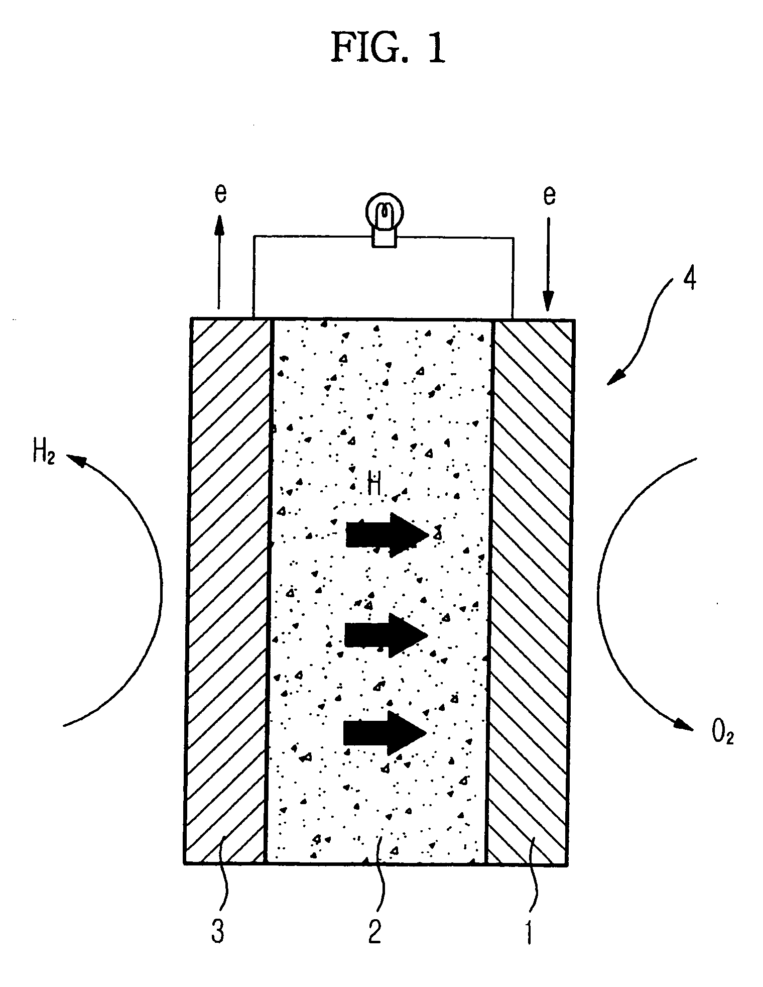
[0052]The stack 20 is an electricity generating device to directly convert chemical energy of hydrogen and oxygen contained in the fuel 80, namely, hydrocarbon-based fuel such as methanol, ethanol, or natural gas into electrical energy in accordance...


PUM


Abstract

A stable air supply system in a fuel cell system produces heat and electricity by combining hydrogen modified from a major raw material selected from various hydrogen compounds, with oxygen existing in air. An air supply device and an air supply method in a fuel cell system, automate a lamda control, and achieve a fuel cell system operation efficiently and stably coping with pressure loss and pulsation occurring within the system, while using a minimum number of balance-of-plant (BOP) units. A method efficiently and precisely supplies air during the start-up and operation of the fuel cell system, while preventing flame failure of a burner and maintaining an appropriate carbon monoxide concentration even when an abrupt flow rate variation occurs. In this regard, an operating method is economical and stable in terms of the costs and configuration of the fuel cell system.

Description


Claims


Application Information

Patent Timeline
Owner SAMSUNG ELECTRONICS CO LTD
Why Eureka
Try Eureka