Auxiliary handle for hand-held power tool

a technology for power tools and auxiliary handles, which is applied in the direction of handbags, manufacturing tools, portable power tools, etc., can solve the problems of increasing the time and adversely affecting the fixation of the power tool, and achieves the effects of convenient actuation simple operation of the unlocking device, and advantageous manufacturing

Active Publication Date: 2010-03-18
HILTI AG
View PDF21 Cites 15 Cited by
  • Summary
  • Abstract
  • Description
  • Claims
  • Application Information

AI Technical Summary

Benefits of technology

[0013]Advantageously, the actuation member is provided on a section of the gripping member, which provides for an easy actuation of unlocking device. More advantageously, the actuation member is provided on a section of the gripping member easily accessible from outside.
[0014]Advantageously, the actuation member is provided at an end of the pivot pin opposite the end on which the tensioning member is arranged. It provides for an advantageous construction of the auxiliary handle and, thus, its advantageous manufacturing. This also insures a simple operation of the unlocking device.
[0015]Advantageously, the actuation member is formed as a pressure knob axially displaceable along the pivot axis of the lag hinge. This provides for an easy actuation of the unlocking device and its operation.
[0016]Advantageously, the locking device includes at least one locking member axially displaceable by the actuation member relative to the pivot axis of the lag hinge and engageable with a section of the gripping member for locking the lag hinge. The at least one locking member has a stop section that, together with a stop counter-section provided on the gripping member, prevents the cooperating parts from rotation relative to each other in the locked position of the lag hinge. Upon actuation of the actuation member, only the connection between the at least one locking member and the gripping member is lifted off, which provides for a simple pivotal movement of the gripping member of the auxiliary handle into a desired position. As soon as the desired position of the gripping member is reached, the at least one locking member is again displaced into its locking position in which it again becomes engaged with the gripping member.

Problems solved by technology

This occupies an increased amount of time.
The drawback of the above-described auxiliary handle consists in that for releasing the lag hinge, the engaging each other, elements of the locking device should be spaced from each other by at least the height of the teeth so that the gripping member can be pivoted relative to the clamping section.
This can lead to loosening of the tightening of the clamping section and thereby adversely affect its fixation on the power tool, so that the auxiliary handle can automatically pivot about an operational axis defined by a working tool.

Method used


Image

  • Auxiliary handle for hand-held power tool
  • Auxiliary handle for hand-held power tool
  • Auxiliary handle for hand-held power tool

Examples


Embodiment Construction

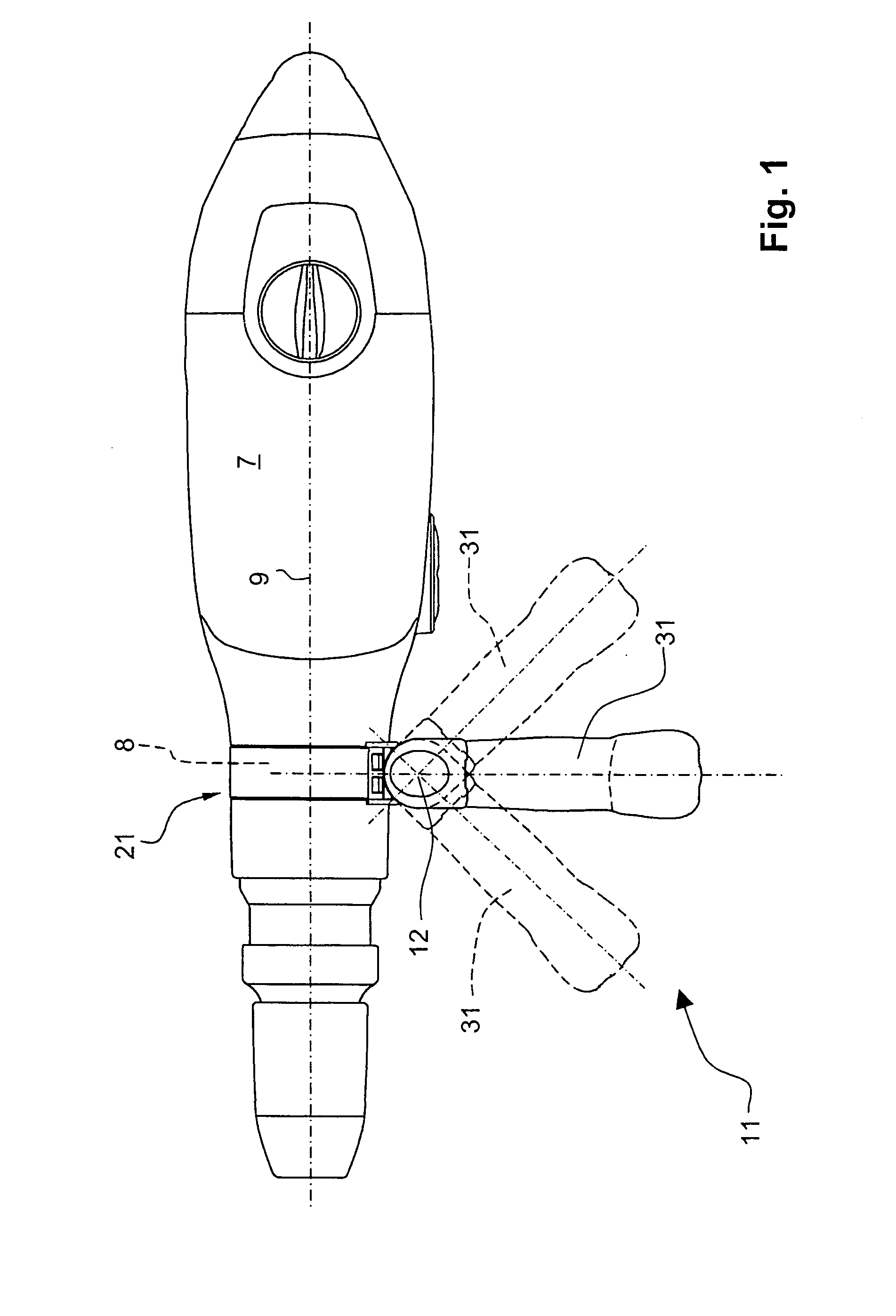
[0029]A hand-held power tool 7, which is shown in FIG. 1, includes an auxiliary handle 11 according to the present invention that is formed as a side handle and is releasably secured on a cylindrical section 8 of the power tool 7. The auxiliary handle 11 has a gripping member 31 for grasping and holding the auxiliary handle 11 and pivotable about a pivot axis 12 toward an operational axis 9 of the power tool 7 to adapt to the gripping position on the power tool 7, when needed.

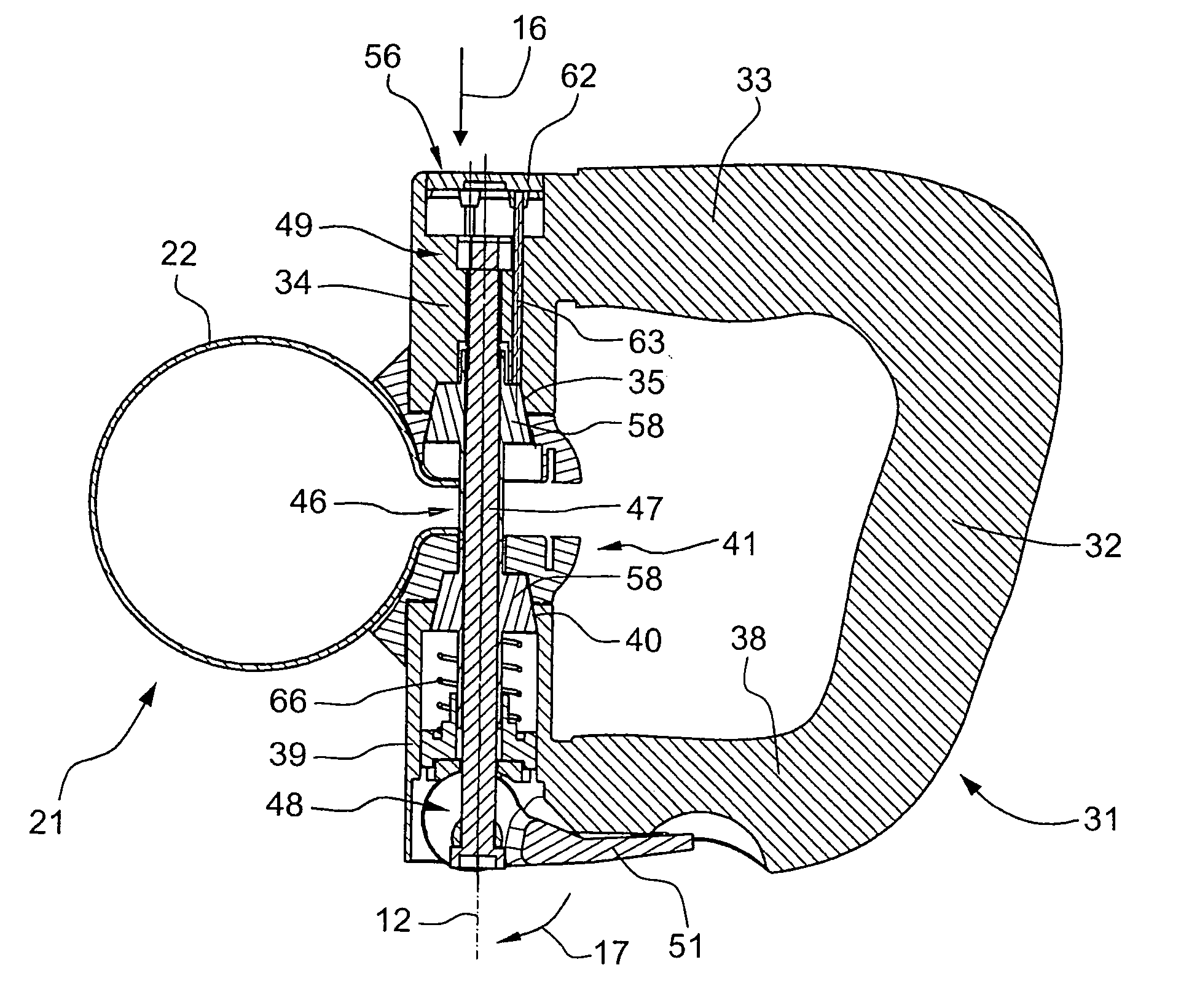
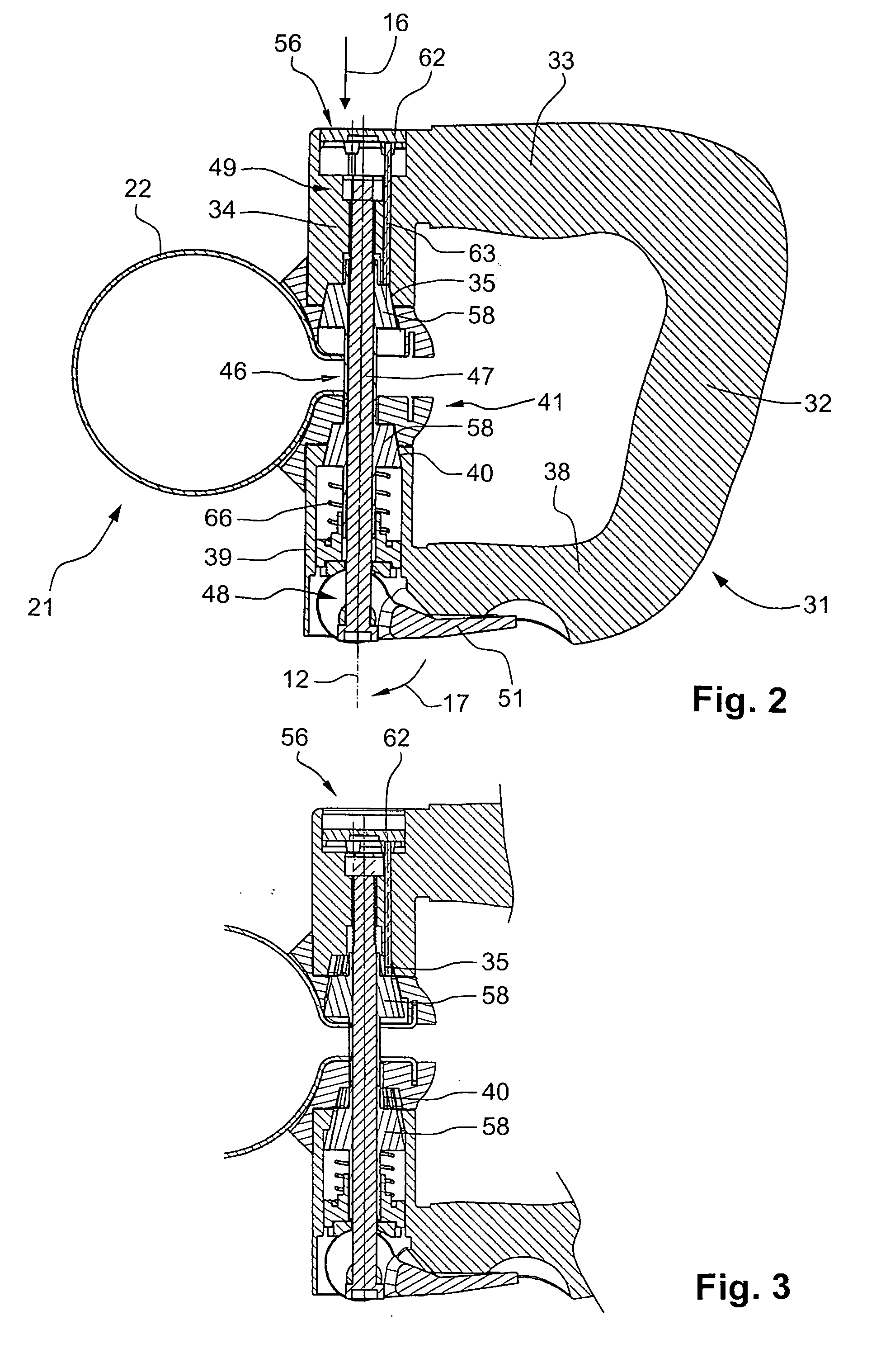
[0030]The auxiliary handle 11 has, as shown in FIGS. 2-3, a clamping section 21 for securing the auxiliary handle 11 on the power tool 7 and having a tightening band 22.

[0031]The gripping member 31 of the auxiliary handle 11 is essentially U- or D-shaped and has a base 32 and two legs 33 and 38 projecting from the base 32. On the leg 33, there is provided a first bearing section 34 adjacent to the second leg 38, and on the leg 38, there is provided a second bearing section 39 adjacent to the first leg 33.

[0032]...


PUM


Abstract

An auxiliary handle for a hand-held power tool (7) includes a lockable lag hinge (46) provided between the clamping section (21) and the gripping member (34) and having a pivot pin (47), a tensioning member (51) for tightening and loosening the clamping section (21) and arranged on an end (48) of the pivot pin (47) of the lag hinge (46), a locking device (41) for locking and releasing the lag hinge (46), and an independent from the tensioning member (51), unlocking device (56) for releasing the locking device (41) and having an actuation member (62) upon actuation of which, the locking device (41) is displaced from its locking position in which the lag hinge (46) is locked to its release position in which the lag hinge (46) is released.

Description

BACKGROUND OF THE INVENTION[0001]1. Field of the Invention[0002]The present invention relates to an auxiliary handle for a hand-held power tool such as a power drill, a hammer drill or a chisel hammer and includes a clamping section for securing the auxiliary handle on a section of the power tool, a gripping member for holding the auxiliary handle, a lockable lag hinge provided between the attachment section and the gripping member and having a pivot pin, a tensioning member for tightening and loosening the clamping section and arranged on an end of the pivot pin of the lag hinge, and a locking device for locking and releasing the lag hinge.[0003]2. Description of the Prior Art[0004]In power tools, auxiliary handles of the type described above are provided, if needed, in form of a side handle mounted, e.g., on a housing section adjacent to a tool holder for guiding the power tool. It is known to form a gripping member of the auxiliary handle pivotable about a pivot axis in order to ...

Claims


Application Information

Patent Timeline
Patent Type & Authority Applications(United States)
IPC IPC(8): B25G1/02
CPCB25F5/026Y10T16/4713Y10T16/469Y10S16/25
Inventor MARTIN
Owner HILTI AG
Why Eureka
Try Eureka