Hybrid environmental conditioning system

a technology of environmental conditioning and hybridization, applied in the direction of domestic cooling apparatus, defrosting, piston pumps, etc., can solve the problems of aircraft fuel consumption, inefficient method of conditioning air, and inefficient use of power to generate unnecessary pressur

Active Publication Date: 2010-03-18
HAMILTON SUNDSTRAND CORP
View PDF31 Cites 14 Cited by
  • Summary
  • Abstract
  • Description
  • Claims
  • Application Information

AI Technical Summary

Problems solved by technology

This method of conditioning air is inefficient.
Generating the unnecessary pressure is inefficient use of power.
As a consequence of the inefficiency of the environmental conditioning system, the aircraft consumes more fuel than necessary.

Method used


Image

  • Hybrid environmental conditioning system
  • Hybrid environmental conditioning system
  • Hybrid environmental conditioning system

Examples


Embodiment Construction

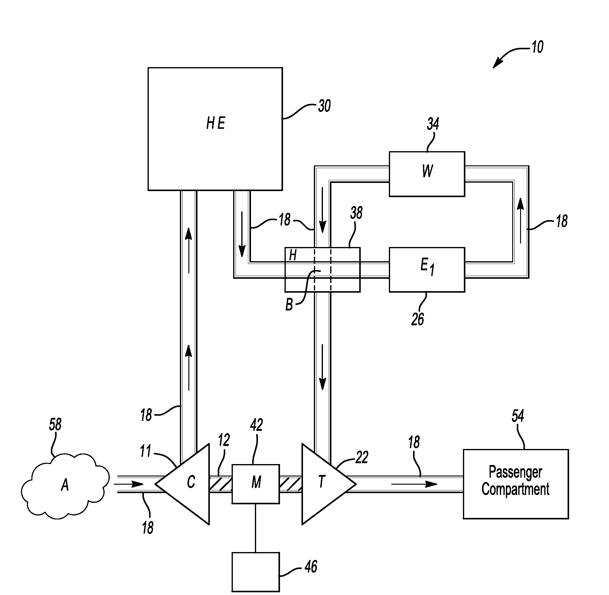
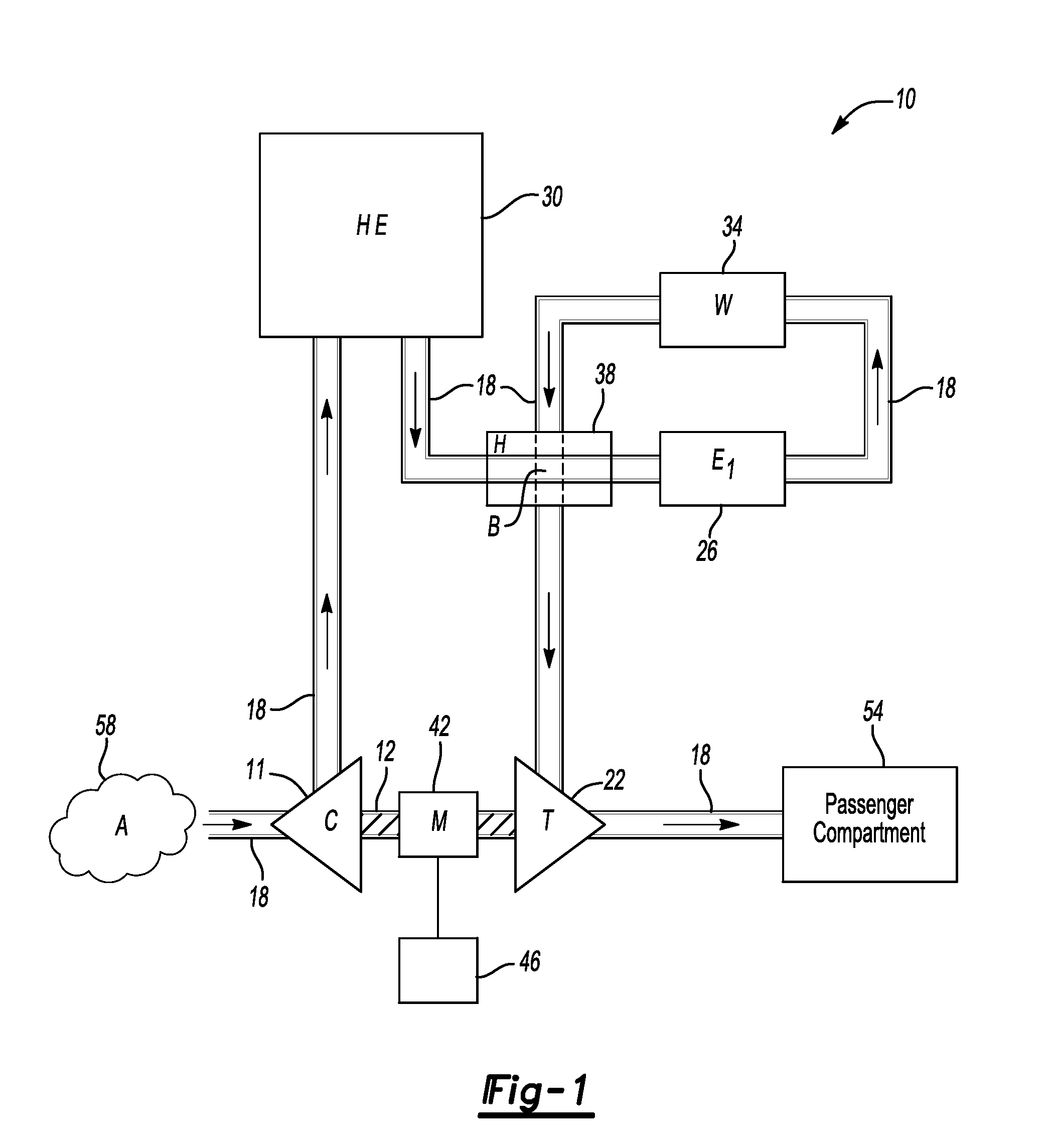
[0009]With reference to FIG. 1, there is shown a schematic view of an inventive environmental conditioning system 10 for a vehicle, such as an aircraft. As shown, there is air flow path 18, through which air is obtained from air source 58 and conditioned for use in passenger compartment 54. In air flow path 18 are compressor 11, heat exchanger 30, reheater 38, evaporator 26, water removal device 34 and turbine 22. Compressor 11 is coupled to turbine 22 by shaft 12. Compressor 11 is driven by turbine 22 and may also receive power from motor 42.

[0010]Air from air source 58, such as an outside air source or bleed air from another compressor (not shown), is communicated to compressor 11. Compressor 11 pressurizes and thereby heats air in air flow path 18 and directs air to heat exchanger 30. Heat exchanger 30, which may be one heat exchanger or a series of heat exchangers, rejects heat to a heat sink and thereby reduces the temperature of air from compressor 11. The heat sink may be coo...


PUM


Abstract

An environmental conditioning system has a compressor for compressor air in an air flow path. A turbine drives the compressor and is coupled to the compressor. An evaporator is in communication with the compressor. The evaporator is configured to cool air from the compressor.

Description

BACKGROUND OF THE INVENTION[0001]This invention relates to an environmental conditioning system for a vehicle, such as an aircraft.[0002]In flight, an aircraft may obtain conditioned air from a compressor of a turbine engine. Bleed air is output at a high temperature from the compressor and is passed through a heat exchanger to lower the air's temperature. The air eventually passes to the passenger compartment. This process of conditioning air from the compressor is known as an air cycle.[0003]This method of conditioning air is inefficient. More energy than is necessary is used to condition the air because the pressure delivered by the engine compressor exceeds the pressure required for adequate conditioning at most operating points and is throttled away. Generating the unnecessary pressure is inefficient use of power. As a consequence of the inefficiency of the environmental conditioning system, the aircraft consumes more fuel than necessary.[0004]A need therefore exists for more e...

Claims


Application Information

Patent Timeline
Patent Type & Authority Applications(United States)
IPC IPC(8): F25D17/06B60H1/32F25D21/14F25B39/02F04B17/00
CPCB64D13/06B64D2013/0618B64D2013/0674B64D2013/0644Y02T50/56Y02T50/50
Inventor BRUNO, LOUIS J.CHRISITANS, DOUGLAS L.
Owner HAMILTON SUNDSTRAND CORP
Why Eureka
Try Eureka