Determining the orientation of an object

a technology of object orientation and orientation, applied in the field of determining the orientation of objects, can solve the problems of inability to detect more than one position, inability to detect multiple points at the same time, and inability to use multi-point detection techniques, etc., and achieve the effect of accurate orientation detection

Inactive Publication Date: 2010-03-18
KONINKLIJKE PHILIPS ELECTRONICS NV
View PDF5 Cites 58 Cited by
  • Summary
  • Abstract
  • Description
  • Claims
  • Application Information

AI Technical Summary

Benefits of technology

[0019]Preferably, the second part of the object is a passage or a hole passing light only in a certain direction and the system is equipped to determine the orientation of the object by using detected light passing through the passage or the hole in a shadow caused by the first part. A passage or a hole passes light only in a certain direction and therefore this embodiment allows a very accurate orientation detection, which is useful for specific applications, such as games that need a particular skill.
[0020]According to an alternative embodiment, the first part of the object is on the outside and is transparent and the second part is on the inside and is opaque. The system is equipped to recognize and / or identify the object by detecting the shape of the second part. The transparent outside of the object does not alter the light that is emitted by the system. In this way the outer shape of the objects used in the system can be identical while the inside can be altered across different objects to allow recognition and / or identification of the object.

Problems solved by technology

With current infrared touch screens it is not possible to detect more than one position at a time, because they use a method that scans a grid built up by LEDs and light sensors.
The detection of multiple points is not possible for all positions, because the selection of one point can block the correct detection of other points.
Therefore, this technique is less usable for multi point detection.
Furthermore, shapes cannot be detected with the current technique; only some form of ‘bounding’ box can in principle be detected in the grid of LEDs and sensors.

Method used


Image

  • Determining the orientation of an object
  • Determining the orientation of an object
  • Determining the orientation of an object

Examples


first embodiment

[0079]According to the invention, which is illustrated in FIG. 10, the object comprises a first opaque part and a second reflective part 42, which is added on the side of the object 16. Arrow 41 points in the direction of the reflective part 42. FIG. 10 shows the object 16 in two opposite positions as illustrated by the arrow 41 pointing in opposite directions.

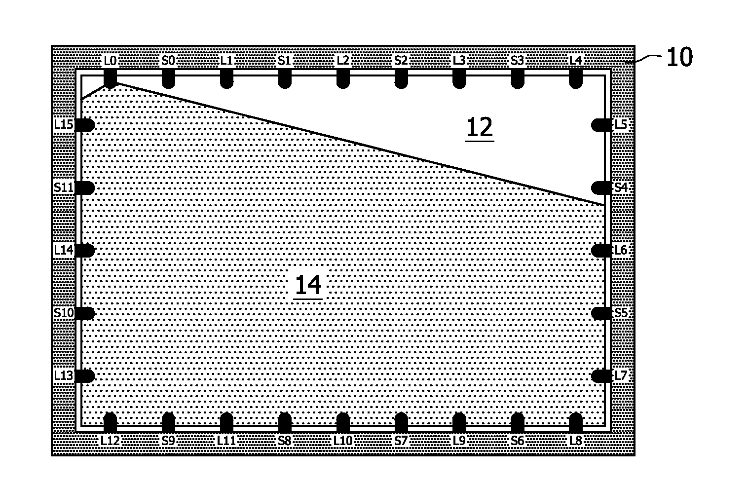
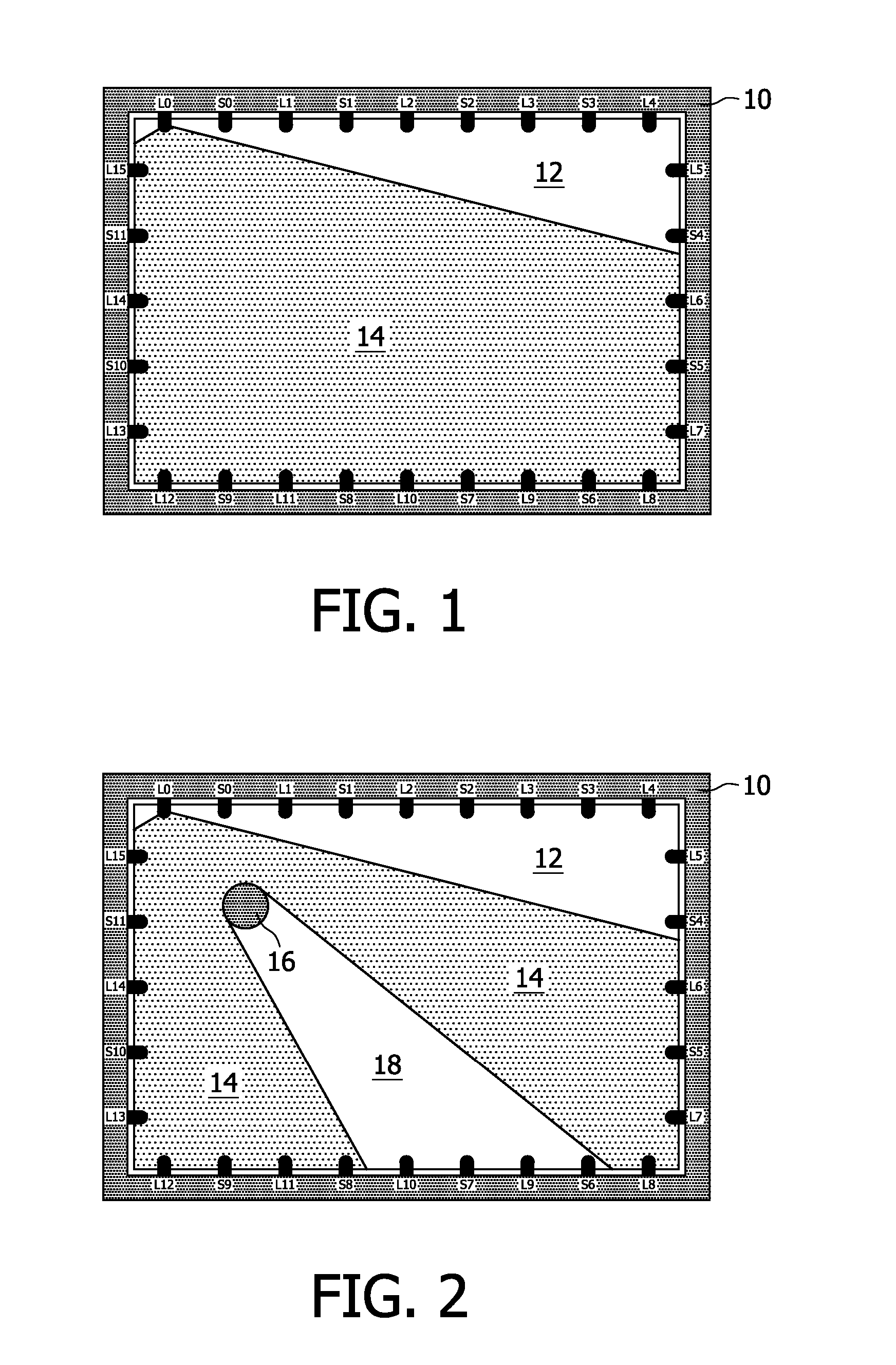
[0080]As a result of the reflective part 42, which functions as an orientation mark of the symmetrical object, the orientation thereof can be detected as illustrated in FIG. 11. As shown in FIG. 11 when the first light source Lo is switched on, object 16 causes a shadow 18 in the same way as illustrated in FIG. 2. However, it will also cause a reflection 70 of a part 60 of the light beam 40. This way the detected result will contain an indication of the orientation of the object. Here the rotation of the object will determine the angle of the reflected light. The sensor in this direction can detect an increase of light intensi...

second embodiment

[0084]Of course non-symmetrical objects are detected including their orientation, but this orientation is rather coarse. According to the invention, an object 16 is provided with a first opaque part and a second transparent part such as a hole or passage 80 that will pass light only in a certain direction, as shown in FIGS. 13 and 14. Accurate detection of the orientation of this passage is possible.

[0085]FIG. 13 illustrates a snapshot of the touch screen display during a point in time at which the first light source L0 is switched on during an operational mode, wherein the object according to a second embodiment of the invention is oriented in a first way. In this orientation, no light of the light beam 14 passes through the passage 80 and a shadow 18 is detected, in the same way as illustrated in FIG. 2. In FIG. 14 the object 16 is oriented in a second way. This orientation gives rise to a detector signal in the middle of the shadow 18, which is detected by sensor S7. It will be a...

third embodiment

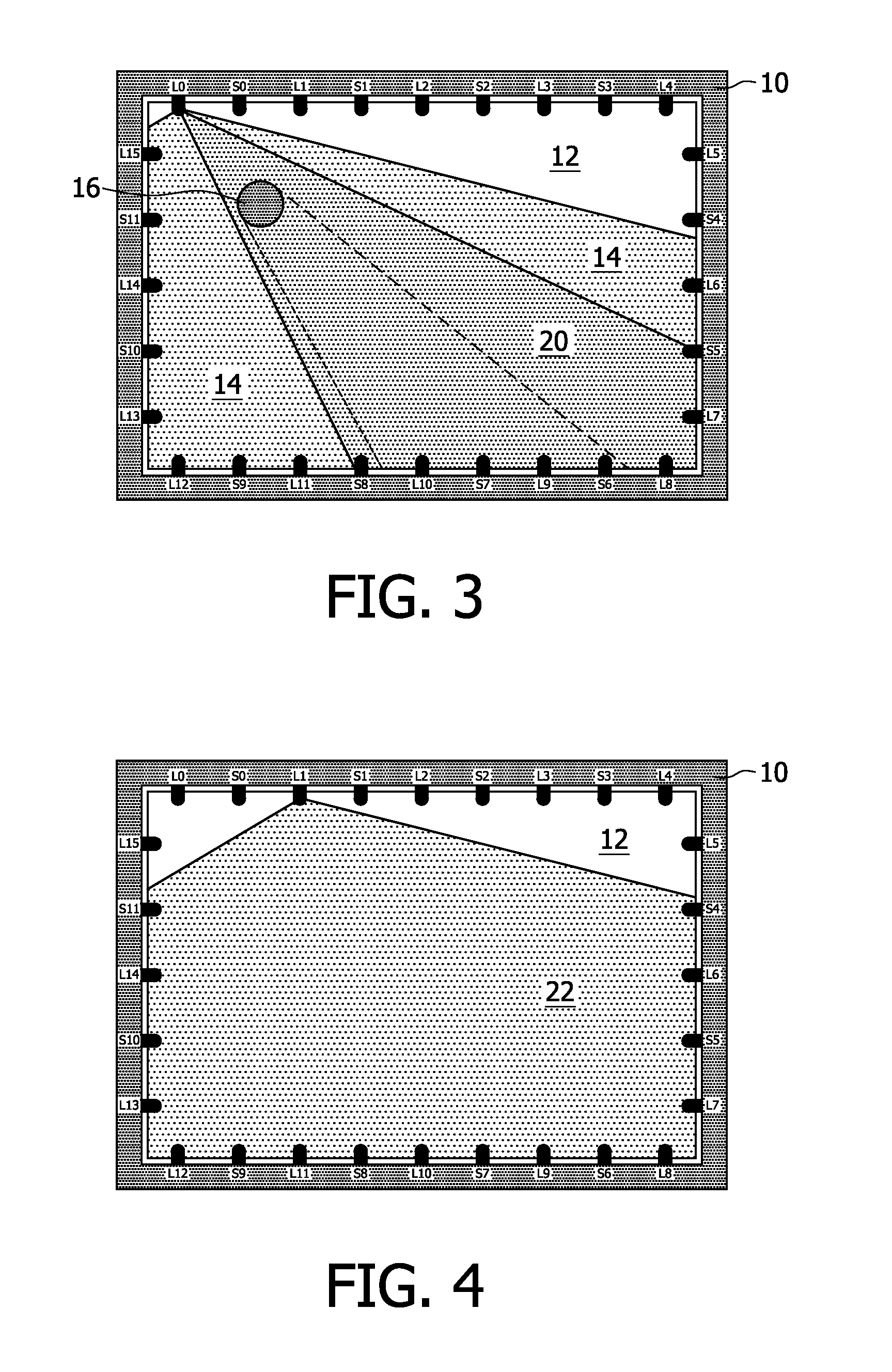
[0086]FIG. 15 illustrates a snapshot of the touch screen display during a point in time at which the first light source L0 is switched on during an operational mode, showing the object 16 according to the invention. Besides the passage 80, the object 16 comprises a mirror 90. This mirror 90 causes a reflection 96 of a first narrow part 92 of the light beam 14 in a first direction, as detected by sensor Si. It causes a reflection 96 of a second narrow part 94 of the light beam 14 in a second direction, as detected by sensor S11.

[0087]By adding multiple options for orientation detection, more orientation information can be gathered by the system and therefore increase the accuracy of the detection or detect orientation of the object in more occasions, e.g. when other objects on the screen block one of the orientation detection options, e.g. the hole in the object.

[0088]According to a fourth and a fifth embodiment of the invention as shown in FIGS. 16 and 17 objects are provided that a...


PUM


Abstract

A touch screen (10) is disclosed comprising a plurality of light emitters (Lo . . . L15) and light detectors (So . . . S11) arranged around a periphery thereof. The position, shape and size of objects (16) may be determined by switching the light emitters on one-by-one and detecting shadows (18) caused by the objects. The objects comprise at least a first part with optical properties of IV a first type and a second part with optical properties of a second different type. By determining the optical phenomena caused by the second part, the orientation of the objects may be determined and/or the objects may be recognized or identified.

Description

BACKGROUND OF THE INVENTION[0001]1. Technical Field[0002]The present invention relates to a system, such as a touch screen system, using light for determining properties of an object placed on a surface. The present invention also relates to an apparatus, object and a method for use in such a system.[0003]2. Description of Related Art[0004]With current infrared touch screens it is not possible to detect more than one position at a time, because they use a method that scans a grid built up by LEDs and light sensors. A position is selected in the grid by interrupting a light beam in horizontal and vertical direction. The detection of multiple points is not possible for all positions, because the selection of one point can block the correct detection of other points. Therefore, this technique is less usable for multi point detection. Furthermore, shapes cannot be detected with the current technique; only some form of ‘bounding’ box can in principle be detected in the grid of LEDs and s...

Claims


Application Information

Patent Timeline
Patent Type & Authority Applications(United States)
IPC IPC(8): A63F3/00G01B11/14
CPCG06F3/0421A63F3/00643
Inventor VAN DE WIJDEVEN, SANDER BERNARD FRANCISBERGMAN, ANTHONIE HENDRIK
Owner KONINKLIJKE PHILIPS ELECTRONICS NV
Why Eureka
Try Eureka