Method and system for shaped glasses and viewing 3D images

a technology of shaped glasses and 3d images, applied in the field of method and system for shaped glasses and viewing 3d images, can solve problems such as crosstalk between

Active Publication Date: 2010-03-18
DOLBY LAB LICENSING CORP
View PDF41 Cites 47 Cited by
  • Summary
  • Abstract
  • Description
  • Claims
  • Application Information

AI Technical Summary

Benefits of technology

[0014]In one embodiment, the present invention provides spectral separation viewing glasses, comprising, a first lens having a first spectral filter, and a second lens having a second spectral filter complementary to the first spectral filter, wherein the first lens and the second lens are each curved to reduce the wavelength shift that occurs when viewing an image at other than an angle normal to a filter through which the image is being viewed. An amount of curvature of the lenses (and hence the filters) is calculated such that viewing angles across a viewing screen are closer to normal angles through the lenses. The curvature is implemented, for example, as a spherical curve.
[0018]In one embodiment, the present invention is a 3D viewing system, comprising, means for projecting spectrally separated images, means for viewing the spectrally separated images through different ocular channels, and means for compensating for wavelength shifts occurring due to viewing angles to portions of the images. The means for compensating may include, for example, means for adjusting an amount of spectral filtering performed on different portions of the image based on viewing angle. The means for compensating includes, for example, means for producing a wavelength mismatch between projector filters and eye filters that compensates for an amount of wavelength shift that occurs in the eye filters due to viewing angle.

Problems solved by technology

The blue shift is undesirable because it can result in crosstalk between left and right images in a 3D image presentation.

Method used


Image

  • Method and system for shaped glasses and viewing 3D images
  • Method and system for shaped glasses and viewing 3D images
  • Method and system for shaped glasses and viewing 3D images

Examples


Embodiment Construction

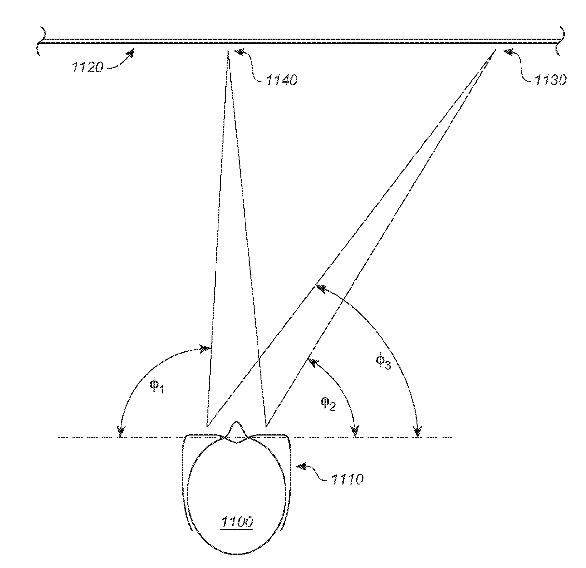
[0038]This invention addresses some of the problems with the Spectral Separation method for projecting 3D images, specifically this invention aims to improve the off-axis filter characteristics when thin film dielectric (interference) filters (e.g., right eye and left eye filters) are used to implement eyewear (e.g., glasses) for viewing spectrally separated images.

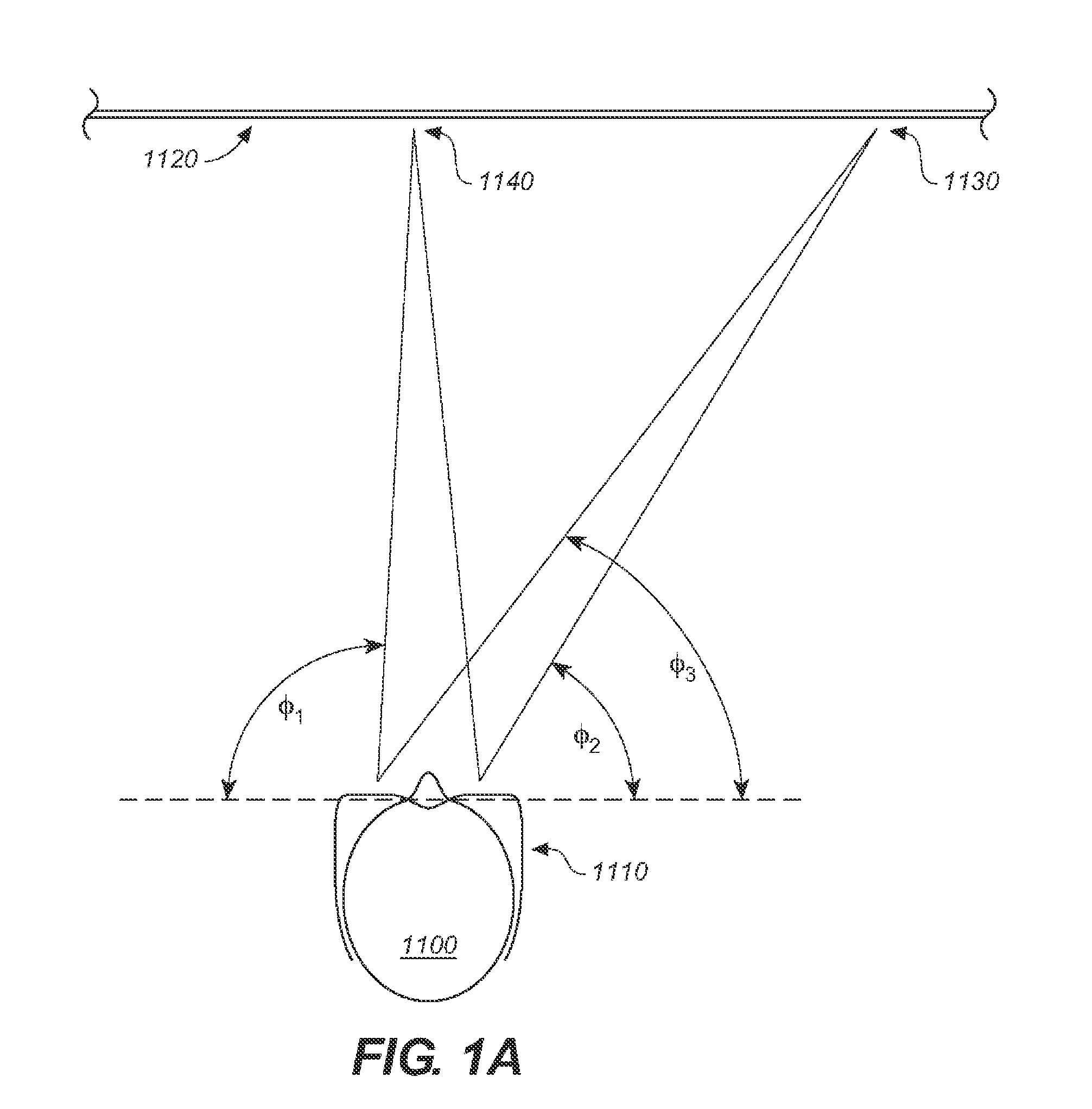
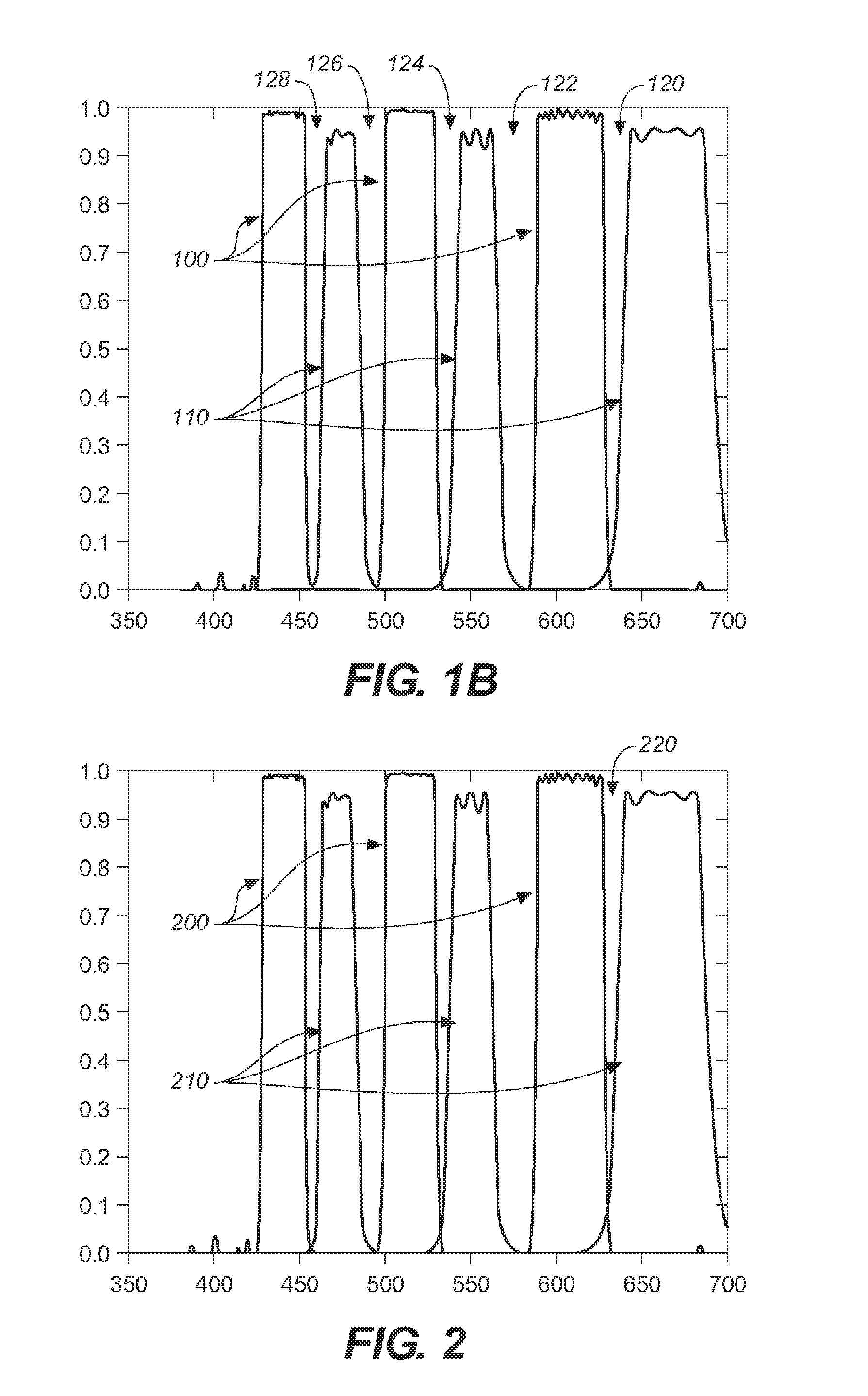
[0039]When light passes through an interference filter at a non- normal angle, the filter characteristics (response shapes, not to be confused with the physical shape of the filter) are changed, and the entire spectral filter response is shifted toward shorter wavelengths (toward the blue). The filter characteristic response shapes are also adversely affected at larger angles. This is a fundamental attribute of interference filters, and can be compensated for by designing the filter for a specific angle if all of the rays are parallel. In cases where the light bundle is not parallel, as in the case with the use of 3-D gla...


PUM


Abstract

Shaped glasses have curved surface lenses and spectrally complementary filters disposed on the curved surface lenses configured to compensate for wavelength shifts occurring due to viewing angles and other sources. The spectrally complementary filters include guard bands to prevent crosstalk between spectrally complementary portions of a 3D image viewed through the shaped glasses. In one embodiment, the spectrally complementary filters are disposed on the curved lenses with increasing layer thickness towards edges of the lenses. The projected complementary images may also be pre-shifted to compensate for subsequent wavelength shifts occurring while viewing the images.

Description

CROSS REFERENCE TO RELATED APPLICATIONS[0001]This application is a divisional of U.S. patent application Ser. No. 11 / 801,574 filed on May 9, 2007, hereby incorporated by reference in its entirety.COPYRIGHT NOTICE[0002]A portion of the disclosure of this patent document contains material which is subject to copyright protection. The copyright owner has no objection to the facsimile reproduction by anyone of the patent document or the patent disclosure, as it appears in the Patent and Trademark Office patent file or records, but otherwise reserves all copyright rights whatsoever.BACKGROUND OF THE INVENTION[0003]1. Field of Invention[0004]The present invention relates viewing systems and products for viewing spectrally separated 3D images. The invention is also related to viewing systems used in a Digital Cinema (D-Cinema) Theatre and improves current methods for projecting a 3D stereoscopic movie.[0005]2. Discussion of Background[0006]Methods for 3D stereoscopic projection include Ana...

Claims


Application Information

Patent Timeline
Patent Type & Authority Applications(United States)
IPC IPC(8): G03B35/26G03B21/00G02B27/22H04N13/363
CPCG02B27/2207G02C7/10G03B35/26G02C7/12H04N13/0459G02B27/22G02C7/107H04N13/0431H04N13/363H04N13/334G02B30/23G02C7/104G02C7/105
Inventor RICHARDS, MARTINALLEN, WILSON HEATON
Owner DOLBY LAB LICENSING CORP
Why Eureka
Try Eureka