Process for detecting detuning at wavelength splitter in optical fibre transmission network and optical fibre transmission network

a wavelength splitter and optical fibre technology, applied in multiplex communication, instruments, optical elements, etc., can solve the problems of reducing the transmission quality of the optical fibre transmission network, the inability to support signals, and the mismatch between filtering features, so as to avoid the significant impairment of data transmission capacity

Inactive Publication Date: 2019-09-17
MITSUBISHI ELECTRIC CORP
View PDF4 Cites 0 Cited by
  • Summary
  • Abstract
  • Description
  • Claims
  • Application Information

AI Technical Summary

Benefits of technology

[0022]Thus, the invention takes advantage of the plurality of sub-carriers for determining quantitatively the detuning which currently exists at the wavelength splitter. Because the wavelength difference between two sub-carriers is less than a wavelength extent of the filtering feature pattern, it is possible to detect and determine quantitatively the detuning extent, namely the shift which exists between the wavelength position of the filtering feature pattern of the wavelength splitter on one hand, and the reference wavelength of the sub-carrier set on the other hand, in a precise and reliable manner. This wavelength shift is determined by using a trial and simulation sequence, and selecting the value tested for the wavelength shift which corresponds to best matching between expected and actual values for the sub-carriers used, after transmission through the wavelength splitter.
[0032]The invention process may be completed with a step / 4 / of updating a setting of at least one tuning parameter of a light source which is used for producing the light carrier, and from which the light sub-carriers are derived through respective modulations applied to the light carrier. These updates of the tuning parameter are performed so as to reduce the wavelength shift which currently exists at the wavelength splitter. Preferably, at least steps / 1 / and / 3 / may be executed in at least one tuning control system which is connected to the optical fibre transmission network, and is separate from the wavelength splitter. Then adjustment commands may be received by tuning means of the light source so as to update the setting of the tuning parameter of the light source. In particular, the tuning control system may be remote from an optical line termination which contains the light source and which is connected to the optical fibre transmission network. Then, the value of the wavelength shift inferred in step / 3 / may be transmitted by the tuning control system to the optical line termination, in control messages which are transmitted by the optical fibre transmission network. Preferably when performing such step / 4 / is contemplated, the update of the setting of the tuning parameter may be triggered only if the value of the wavelength shift as inferred in step / 3 / is higher than a first threshold, in absolute value. This avoids implementing very small changes in the tuning parameter, which may not improve significantly the transmission quality but may cause temporary reductions in the transmission capacity. Optionally, the update of the setting of the tuning parameter may also be triggered if a wavelength shift time-derivation assessed from several wavelength shift values which have been inferred successively, is higher than a second threshold, in absolute value. Implementing such second trigger condition which is based on the time-derivation avoids that the detuning increases too much before retuning of the light source is started.

Problems solved by technology

Then, the wavelength splitter may be capable to transfer the signals supported by one light carrier downstream from the optical line termination to the optical network unit during a time period, and may be no longer capable of transferring signals supported by the same light carrier, from the same optical line termination to the same optical network unit, after one environment parameter has varied in an uncontrolled manner.
Such operation failure is called detuning by the Man skilled in the art, thereby indicating that uncontrolled variations at the wavelength splitter has caused a mismatch between the filtering feature of the wavelength splitter and the light carrier wavelength implemented by the optical line termination.
For both downstream and upstream signals, detuning decreases the transmission quality of the optical fibre transmission network, and can even inhibit the transmission capacity.
However, any system designed for compensating for the variations of at least one environment parameter is power-consuming, and therefore must be supplied with energy, most often with electrical power, from a power source.
But implementing such energy supply may be complicated and very expensive for some locations of the wavelength splitter, for example when it is far from inhabited areas.
But then, a challenge consists in detecting a detuning which may appear between the light carrier as currently produced by the optical line termination and the actual filtering feature of the wavelength splitter.
An additional issue is then to compensate for such detuning for restoring maximum transmission capacity through the wavelength splitter.

Method used


Image

  • Process for detecting detuning at wavelength splitter in optical fibre transmission network and optical fibre transmission network
  • Process for detecting detuning at wavelength splitter in optical fibre transmission network and optical fibre transmission network
  • Process for detecting detuning at wavelength splitter in optical fibre transmission network and optical fibre transmission network

Examples


Embodiment Construction

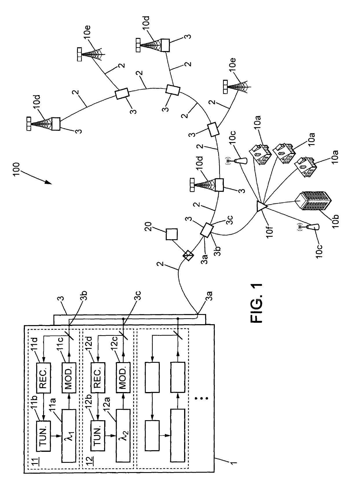
[0043]FIG. 1 shows an optical fibre transmission network 100 in which the present invention can be applied. This network may meet the provisions of the ITU-T G.989 series and IEEE802.3av specifications. For clarity sake, connections from only one optical line termination to several optical network units are shown. The optical line termination 1 may be a central office for example. The optical network units 10a-10e may be residential (10a) or office (10b) facilities, for example with Fiber-To-The-Home connection type, small cell stations (10c), connected through a power splitter 10f, and 5G mobile base stations, either with fronthauling (10d) or backhauling (10e) architecture. Each optical network unit 10a-10e is connected to the optical line termination 1 through optical fibres 2 and wavelength splitters 3.

[0044]The optical line termination 1 may contain several monochromatic light sources, most often of tunable laser type, with respective wavelength values which are different from ...


PUM


Abstract

A process for detecting a detuning which currently exists at a wavelength splitter within an optical fiber transmission network, comprises assessing expected values relating to at least two light sub-carriers, and determining actual values relating to said at least two light sub-carriers. A wavelength shift value which quantifies the existing detuning is obtained from a comparison between the expected and actual values. The process may be completed with updating a tuning of a light source from which the sub-carriers are derived, so as to reduce the wavelength shift.

Description

TECHNICAL FIELD[0001]The present invention relates generally to optical fibre transmission networks, and more particularly to tuning the carrier wavelength to be used by an optical line termination to communicate with an optical network unit through a wavelength splitter.BACKGROUND ART[0002]Optical fibre transmission networks, and more particularly those of passive optical network type, are increasingly used to provide network access to residential or office gateways, or to ensure mobile front- and / or backhauling.[0003]In an attempt to increase the number of users served through one access system to the network, wavelength division multiplexing technologies have been developed. These technologies take advantage of multiplexing several signals using different light carrier wavelengths in one optical fibre. Then, a wavelength splitter is used to select the signals supported by one light carrier and direct them to the intended user device. To this purpose, the wavelength splitter is pl...

Claims


Application Information

Patent Timeline
Patent Type & Authority Patents(United States)
IPC IPC(8): H04J14/02G02B6/12H04B10/079
CPCG02B6/12033H04J14/0242H04B10/07957
Inventor FROC, GWILLERM
Owner MITSUBISHI ELECTRIC CORP
Why Eureka
Try Eureka