Shift lever assembly with electronic detection of modes of transmission

a technology of electronic detection and shift lever, which is applied in the direction of gearing elements, control devices, vehicle components, etc., can solve the problems of increasing the risk of mistakes in detecting the position of the shift lever, and achieve the effect of improving the accuracy of the detection of the position, and accurate and reliable manner

Inactive Publication Date: 2018-05-15
KONGSBERG AUTOMOTIVE AB (SE)
View PDF8 Cites 0 Cited by
  • Summary
  • Abstract
  • Description
  • Claims
  • Application Information

AI Technical Summary

Benefits of technology

[0011]The object of the present invention is to eliminate or at least to minimize the problems described above. This is achieved through a shift lever assembly and a method for assembling a shift lever assembly according to the appended independent claims. Thereby, an improved shift lever assembly can be created, where the detection of a position of a shift lever is performed in a more accurate and reliable manner, thanks to a displaceable mounting of a second member and the subsequent fixing of the second member into a predetermined position in relation to a detent track.
[0012]In one embodiment of the invention, a carrier body holding the second member is arranged to pivot about the same axis as the shift lever. Thereby, an adjustment of the carrier body and thus of the second member in relation to the shift lever can be facilitated and improved.
[0013]In one embodiment of the invention, a housing comprises a first interaction portion and the carrier body comprises a second interaction portion, said first and second interaction portions being arranged to interact to fixate the carrier body in said predetermined position in relation to the detent track. Thereby, the accuracy of the detection of a position of the shift lever can be further improved.

Problems solved by technology

Often, however, it is difficult to achieve the desired results over long stretches of time using cost efficient components, and due to the tolerances of manufacturing and assembling the shift lever assembly, the risk for mistakes in detecting a position of the shift lever increases.

Method used


Image

  • Shift lever assembly with electronic detection of modes of transmission
  • Shift lever assembly with electronic detection of modes of transmission
  • Shift lever assembly with electronic detection of modes of transmission

Examples


Embodiment Construction

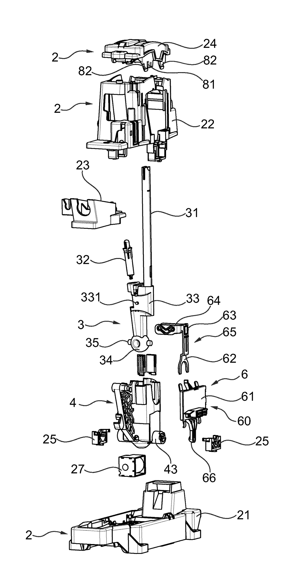
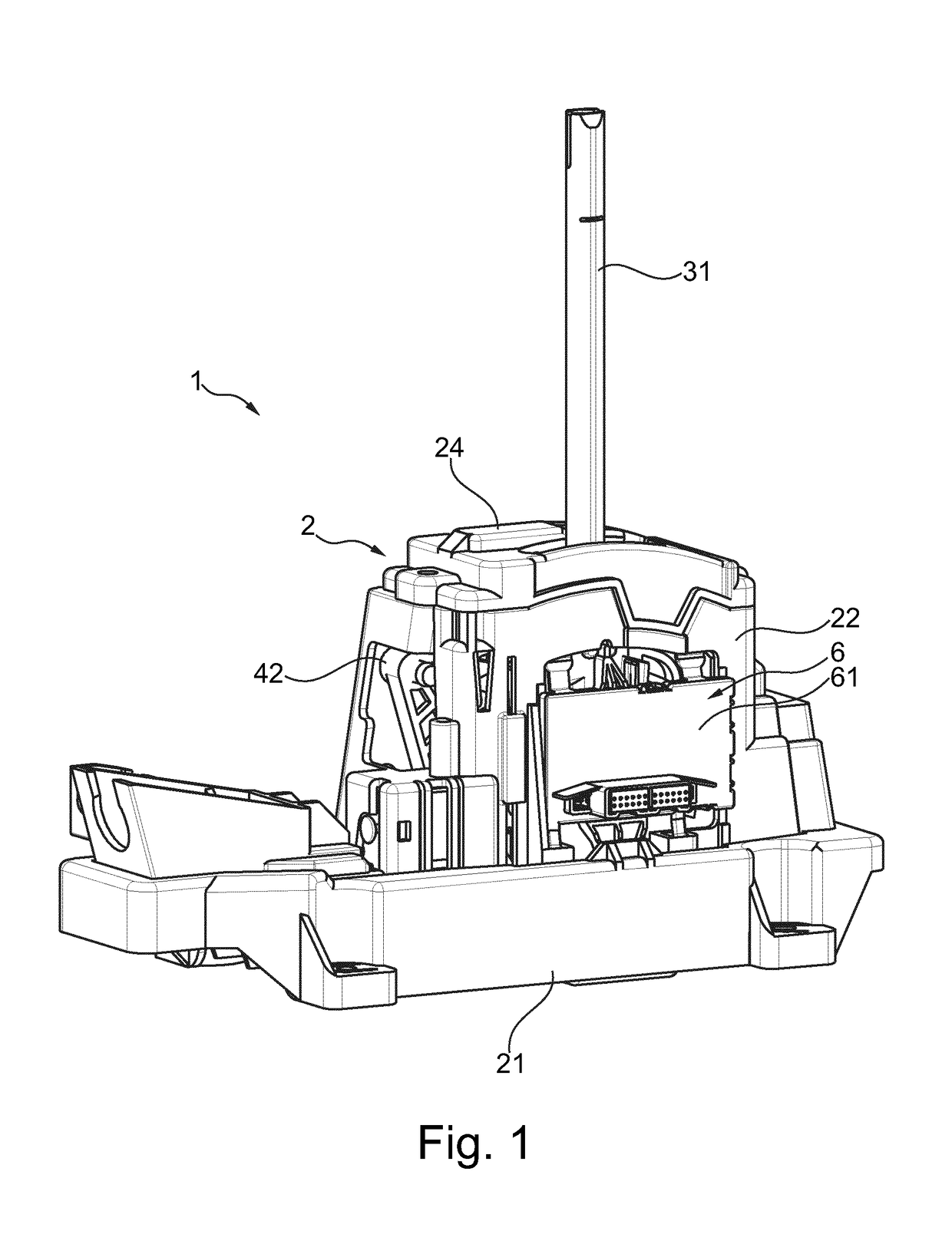
[0029]FIGS. 1 and 2 disclose a preferred embodiment of a shift lever assembly 1 with a housing 2, a shift lever unit 3, cable unit 4 and sensor assembly 6 that when mounted form an assembled shift lever assembly 1 as shown by FIG. 1. The shift lever unit 3 comprises a shift lever 31 and detent plunger 32 that are mounted in an overmold 33 extending towards a ball 34 of a ball joint with pegs 35. Said shift lever unit 3 is mounted in the cable unit 4 so that the ball 34 rests at a seat of the cable unit 4 and is arranged to pivot about a first axis α (see FIG. 6b). The shift lever 31 is arranged to pivot between a number of positions in a first gate, each position corresponding to a mode of transmission. Furthermore, the cable unit 4 is held by a base 21 of the housing 2 by means of receiving portions 25 that allow the cable unit 4 to pivot. Also provided is the sensor assembly 6 having a first member carrier 65, connected to the shift lever 31, and a carrier body 60 that is displace...


PUM


Abstract

The present invention relates to a shift lever assembly for controlling the transmission of a vehicle, said shift lever assembly (1) comprising a housing (2) comprising a detent track (290) having a number of seats, a shift lever (31) arranged to pivot about a first axis (α), located within said housing (2), along a first gate (73) between a number of positions corresponding to different modes of transmission, the positions of the shift lever (31) corresponding to one position each along said detent track (290), a sensor assembly (6) for detecting the position of the shift lever (31) in relation to said detent track (290), said sensor assembly (6) comprising a first member (63) connected to and jointly displaceable with said shift lever (31) along said first gate (73), and a second member (69) mounted on a carrier body (60), said first member (63) and said second member (69) being arranged to interact for detecting the position of the shift lever (31) in relation to said detent track (290), wherein said carrier body (60) is displaceable in at least one direction within said housing (2) in a first stage of assembly and is arranged to be fixed in said direction at a predetermined position in relation to said detent track (290) in a second stage of assembly.

Description

[0001]The subject patent application claims priority to and all the benefits of International Patent Application No. PCT / EP2013 / 068638, filed on Sep. 9, 2013, the disclosure of which is incorporated herein by reference in its entirety.TECHNICAL FIELD[0002]The present invention relates to a shift lever assembly for controlling the transmission of a vehicle, said shift lever assembly comprising[0003]a housing comprising a detent track having a number of seats,[0004]a shift lever arranged to pivot about a first axis, located within said housing, along a first gate between a number of positions corresponding to different modes of transmission, the positions of the shift lever corresponding to one seat each along said detent track,[0005]a sensor assembly for detecting the position of the shift lever in relation to said detent track, said sensor assembly comprising a first member connected to and jointly displaceable with said shift lever along said first gate, and a second member mounted...

Claims


Application Information

Patent Timeline
Patent Type & Authority Patents(United States)
IPC IPC(8): B60K20/00F16H59/10F16H59/02F16H59/04F16H61/24
CPCF16H59/0204F16H59/105F16H61/24F16H2061/247F16H2059/026
Inventor GRENNVALL, ANDREAS
Owner KONGSBERG AUTOMOTIVE AB (SE)
Why Eureka
Try Eureka