
Network control apparatus, method, and program

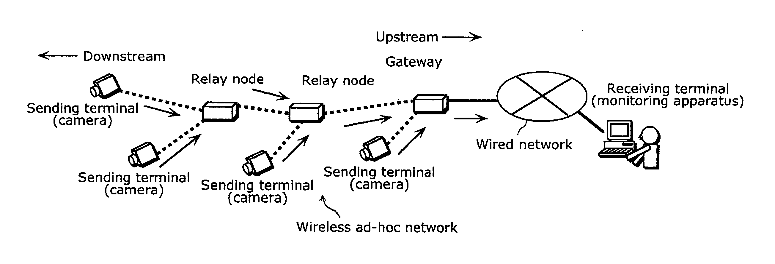
a network control and network control technology, applied in the field of network control apparatus, method and program, can solve problems such as unfairness among sending terminals, achieve the effects of reducing setting operations, maintaining fairness in service quality, and excelling responsiveness

Active Publication Date: 2010-03-18
PANASONIC CORP
View PDF1 Cites 24 Cited by
  • Summary
  • Abstract
  • Description
  • Claims
  • Application Information

AI Technical Summary

Benefits of technology

[0033]As described above, the network control apparatus according to the present invention estimates a bottleneck by use of routing information that is used for establishing ad-hoc routing, thus enabling bottleneck estimation that excels in both follow-up ability to follow changes in an ad-hoc network and globality. In addition, it is possible to perform, only on a relay apparatus estimated as the bottleneck, measurement of an effective band for the route to the gateway and allocate an effective band to each terminal apparatus by dividing the measured effective band, thus enabling transmission band allocation that excels in responsiveness.
[0034]As a result, in the wireless ad-hoc network, it becomes possible to automate transmission band allocation in which fairness among terminals is secured, and efficient transmission band allocation over the entire wireless ad-hoc network.
[0035]With this, even when there are a large number of terminals to be controlled and resetting of the transmission band is necessary as a result of addition and deletion of a terminal or a network, no complicated manual band settings for the terminals and the relay nodes (setting of the communication speed) are required, thus reducing setting operations.
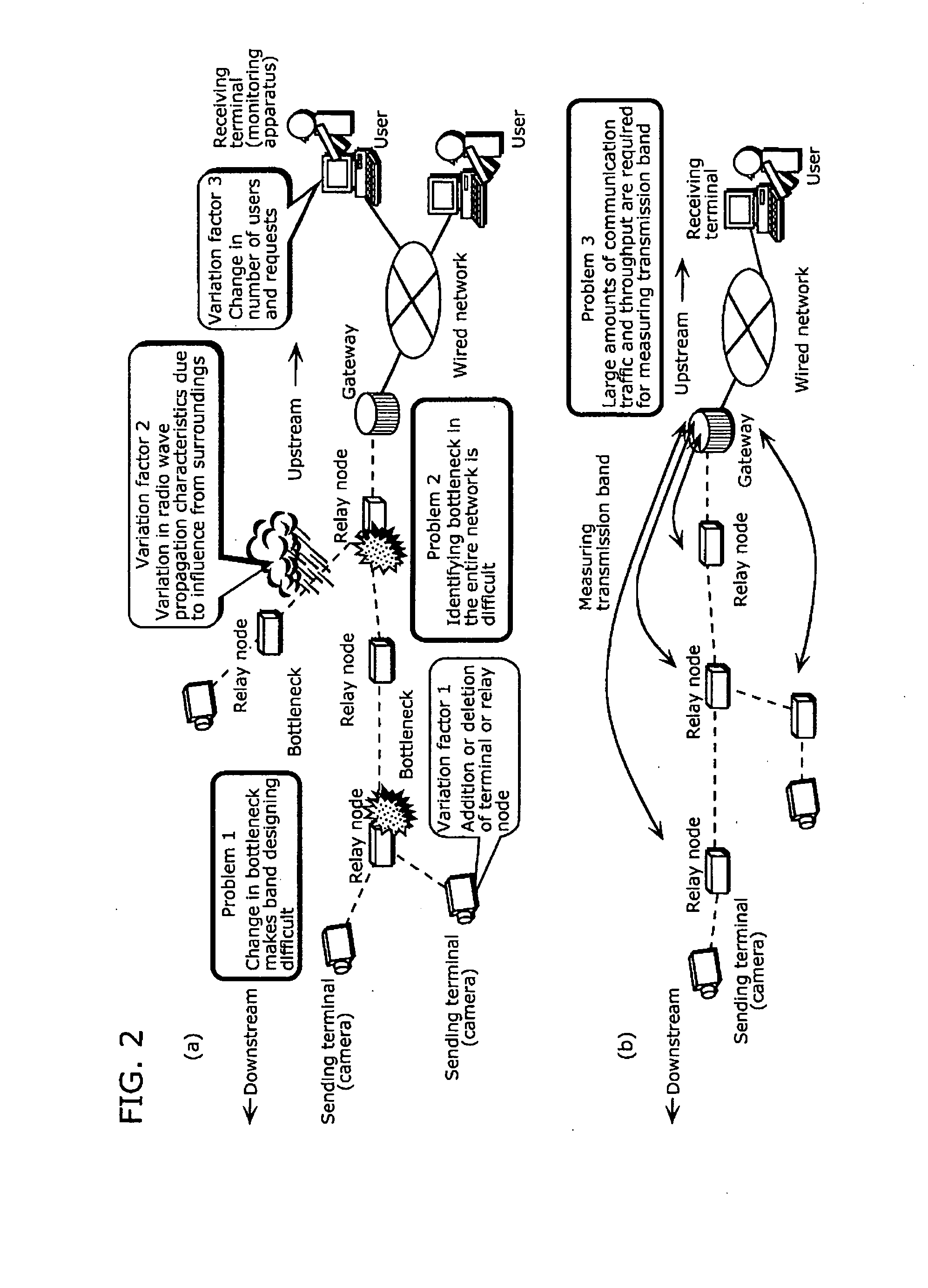
[0036]In addition, when packet loss occurs due to a transmission error caused by variation in radio wave propagation characteristics between relay nodes relaying from the sending terminal to the gateway, or when a bottleneck is generated on the transmission path due to congestion caused by the traffic flowing into a relay node located on the way or by packet loss, it is possible for each terminal to automatically maintain fairness in quality of service (QoS) in communication and efficient allocation of the transmission band.
[0037]In addition, particularly, in estimating the bottleneck by comparing transmission error rates at data links, which are obtained from the routing information, it is possible to measure an effective band for the bottleneck in the wireless ad-hock network and allocate bands to plural sending terminals according to the effective band, thus allowing transmission of the traffic data without causing any deterioration in transmission quality, such as packet loss or delays due to congestion.

Problems solved by technology

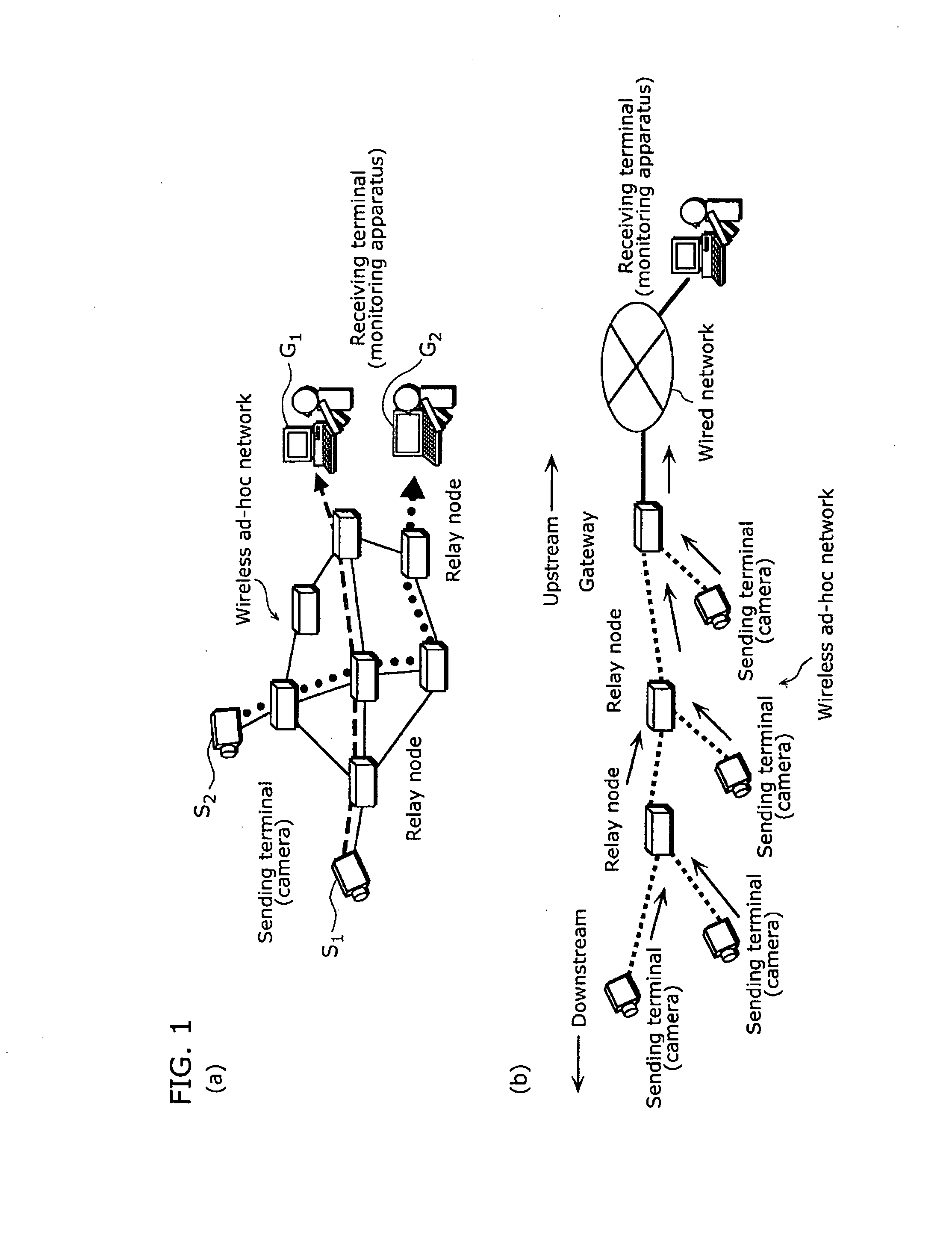
In the transmission, an effective band available for the data transmission between each of the sending and receiving terminals depends on routing from the sending terminal to the gateway and the network status, thus resulting in unfairness among the sending terminals.

Method used


Image

  • Network control apparatus, method, and program
  • Network control apparatus, method, and program
  • Network control apparatus, method, and program

Examples


first embodiment

[0107]FIG. 3 is a functional block diagram showing an example of a configuration of a network control apparatus 40 in a first embodiment.

[0108]The network control apparatus 40 is dispersedly provided in: a gateway, a relay node, and a terminal making up a wireless ad-hoc network portion of the network system (FIG. 1(b)). The wireless ad-hoc network is controlled by the network control apparatus 40 of the present invention. The network control apparatus 40 may also be dispersedly provided in plural relay nodes having an identical structure and plural terminals having an identical structure.

[0109]Hereinafter, a major portion of the network control apparatus 40 that is dispersed in the gateway, the relay node, and the terminal shall be described.

[0110]The gateway includes: a band estimating unit 401, a routing processing unit 402, a bottleneck estimating unit 411, a band allocation determining unit 403, and a gateway control unit 404, which function as the network control apparatus 40....

second embodiment

[0252]FIG. 20 is a functional block diagram showing an example of a configuration of a network control apparatus 41 in a second embodiment of the present invention.

[0253]The network control apparatus 41 of the second embodiment is different from the network control apparatus 40 of the first embodiment shown in FIG. 3 in that: a terminal performs the estimation of a relay node to be the bottleneck on the transmission path, which is performed by the bottleneck estimating unit 411 of the gateway in the first embodiment. Hereinafter, the same configuration as in FIG. 3 is assigned with the same numeral and the description thereof shall be omitted, and a different configuration shall be described in detail.

[0254]The terminal of the second embodiment includes: a bottleneck estimating unit 412 and a band allocation determining unit 413 in addition to the transmission rate control unit 408, the data generating unit 409, and the terminal control unit 410.

[0255]The bottleneck estimating unit ...


PUM


Abstract

To enable network control (particularly, transmission band allocation) that excels in follow-up ability to follow changes in a network, locality, and responsiveness. A network control apparatus controls a wireless ad-hoc network and includes: a routing processing unit (402) which establishes routing within a wireless ad-hoc network using routing information including information regarding a local transmission quality within the wireless ad-hoc network; a routing processing unit (406) which obtains the information regarding the transmission quality from the routing information used for establishing the routing; and a bottleneck estimating unit (411) which estimates a relay apparatus as a bottleneck candidate, based on a distribution of plural transmission qualities within the wireless ad-hoc network, which are indicated by the obtained information.

Description

TECHNICAL FIELD[0001]The present invention relates to a technique for performing allocation of an appropriate transmission band between nodes making up an ad-hoc network.BACKGROUND ART[0002]Conventionally, a wireless ad-hoc network and a wired network are connected to each other at a gateway, and data is transmitted from plural sending terminals connected to the wireless ad-hoc network to respective receiving terminals connected to the wired network.[0003]In the transmission, an effective band available for the data transmission between each of the sending and receiving terminals depends on routing from the sending terminal to the gateway and the network status, thus resulting in unfairness among the sending terminals.[0004]In order to reduce such unfairness, various techniques are known for securing fairness in transmission band among plural sending terminals connected to the wireless ad-hoc network (for example, see Patent References 1 to 6).[0005]Patent Reference 1 discloses a te...

Claims


Application Information

Patent Timeline
Patent Type & Authority Applications(United States)
IPC IPC(8): H04L12/56H04L45/125H04W24/00H04W40/12H04W40/22H04W84/12H04W84/18
CPCH04L43/0847H04L43/0882H04L45/125H04W40/22H04L2012/40273H04W40/12H04W40/14H04L45/70
Inventor YOSHIDA, ATSUSHIYAMAGUCHI, TAKAOAOKI, KATSUJI
Owner PANASONIC CORP
Learn More