Cooling structure for outer surface of a gas turbine case

a technology of cooling structure and gas turbine, which is applied in the direction of machines/engines, continuous jet plants, liquid fuel engines, etc., can solve the problems of shaft rotation and increase the cost of production and maintenance of the combustor assembly

Active Publication Date: 2010-03-18
SIEMENS ENERGY INC
View PDF19 Cites 17 Cited by
  • Summary
  • Abstract
  • Description
  • Claims
  • Application Information

AI Technical Summary

Problems solved by technology

The expansion of the working gas through the rows of rotating blades and stationary vanes in the turbine assembly results in a transfer of energy from the working gas to the rotating assembly, causing rotation of the shaft.
Hence, an increase in the case temperature could require specification of higher temperature materials, such as nickel based alloys, for the compressor / combustor case, resulting in increased costs for the production and maintenance of the combustor assembly.

Method used


Image

  • Cooling structure for outer surface of a gas turbine case
  • Cooling structure for outer surface of a gas turbine case
  • Cooling structure for outer surface of a gas turbine case

Examples


Embodiment Construction

[0014]In the following detailed description of the preferred embodiment, reference is made to the accompanying drawings that form a part hereof, and in which is shown by way of illustration, and not by way of limitation, a specific preferred embodiment in which the invention may be practiced. It is to be understood that other embodiments may be utilized and that changes may be made without departing from the spirit and scope of the present invention.

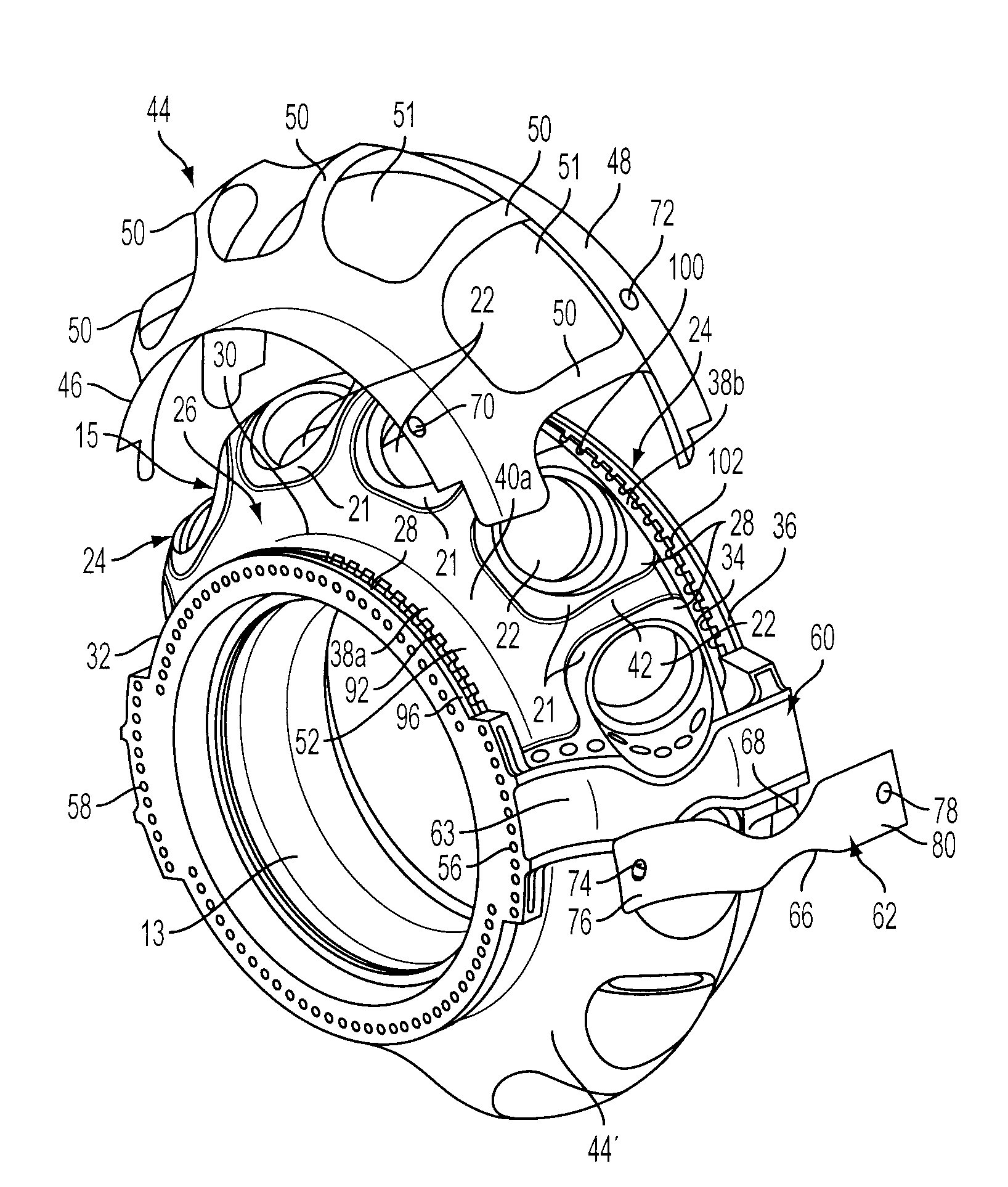
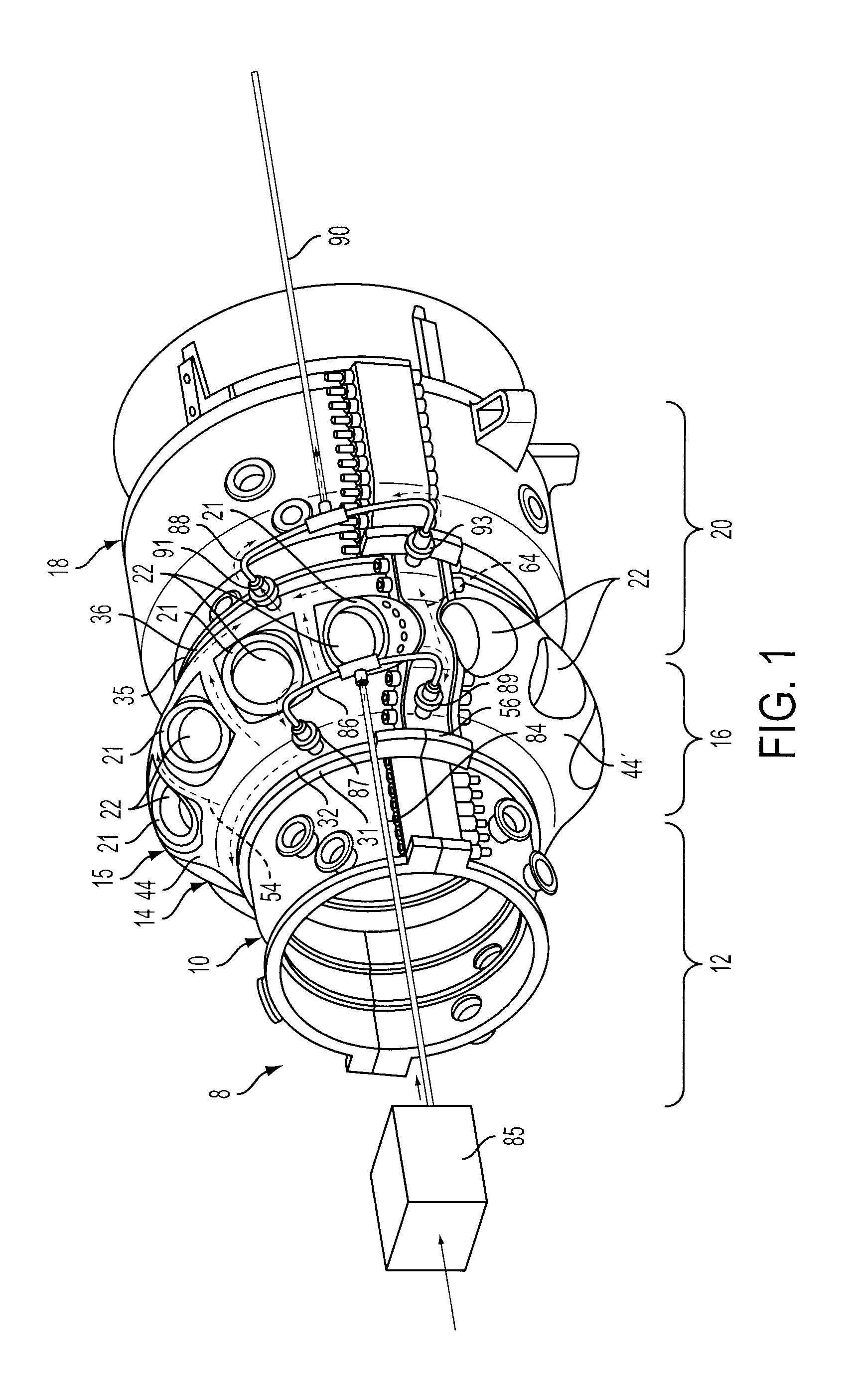
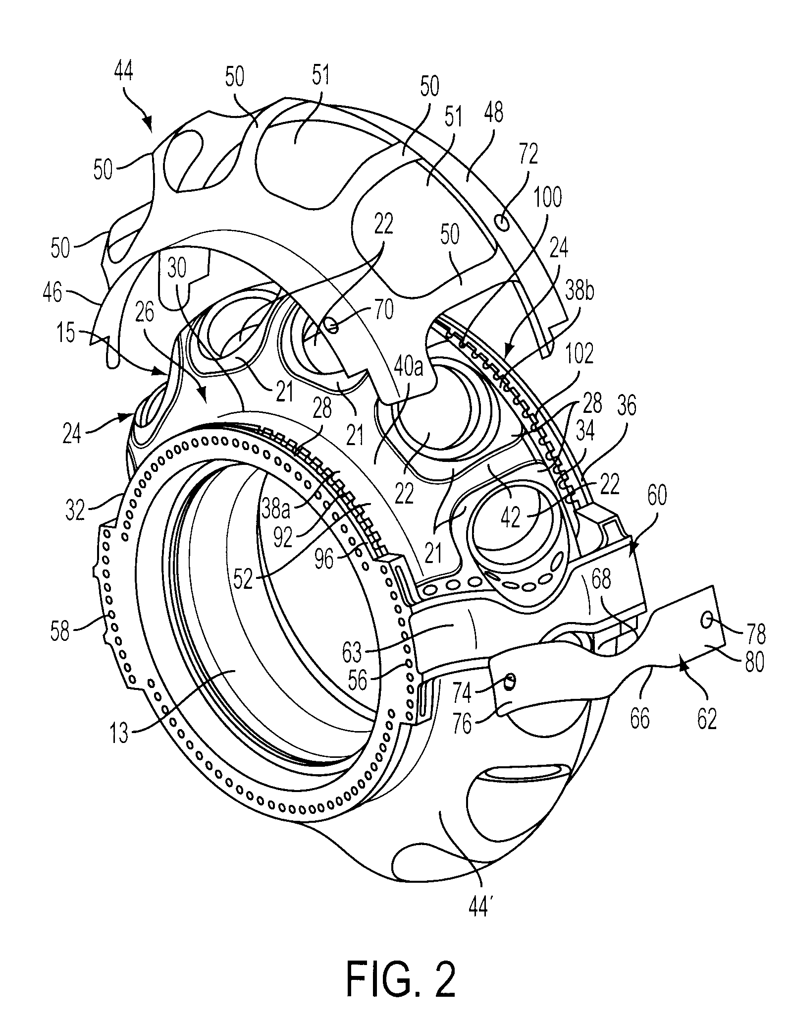
[0015]Referring to FIG. 1, a gas turbine engine assembly 8 is shown including an intermediate case 10 defining an outer case for a downstream portion of a compressor section 12 of a turbine engine (the upstream portion of the compressor section 12 is not shown), a compressor / combustor case 14 defining an outer case for a combustor section 16 of the turbine engine and for an outlet portion of the compressor section 12, and a turbine case 18 defining an outer case for a turbine section 20 of the turbine engine. As is known in the art, the ...


PUM


Abstract

A gas turbine case is provided including an outer case surface, and a channel portion formed as a recessed area extending radially inwardly into the outer case surface. The channel portion extends about a circumference of the case. An outer flow jacket is attached to the outer case surface and extends over the channel portion to define an enclosed cooling passage along the outer case surface. At least one inlet passage and at least one outlet passage are provided in fluid communication with the enclosed cooling passage to convey air to and from the cooling passage.

Description

FIELD OF THE INVENTION[0001]The present invention relates to gas turbine engines and, more particularly, to a structure for providing cooling to a case forming a section of a gas turbine engine.BACKGROUND OF THE INVENTION[0002]Generally, gas turbine engines have three main sections or assemblies, including a compressor assembly, a combustor assembly, and a turbine assembly. In operation, the compressor assembly compresses ambient air. The compressed air is channeled into the combustor assembly where it is mixed with a fuel and ignites, creating a heated working gas. The heated working gas is expanded through the turbine assembly. The turbine assembly generally includes a rotating assembly comprising a centrally located rotating shaft and a plurality of rows of rotating blades attached thereto. A plurality of stationary vane assemblies, each including a plurality of stationary vanes, are connected to a casing of the turbine assembly and are located interposed between the rows of rota...

Claims


Application Information

Patent Timeline
Patent Type & Authority Applications(United States)
IPC IPC(8): F02C7/18F01D25/12
CPCF01D25/145F01D25/14
Inventor SHTEYMAN, YEVGENIYTSAI, FRANKMARSHALL, JAMES F.SMITH, SCOTT W.
Owner SIEMENS ENERGY INC
Why Eureka
Try Eureka