

Method for configurating a feedback region in wireless communication system
- Summary
- Abstract
- Description
- Claims
- Application Information
AI Technical Summary
Benefits of technology
Problems solved by technology
Method used
Image

Examples
Embodiment Construction
Technical Problem
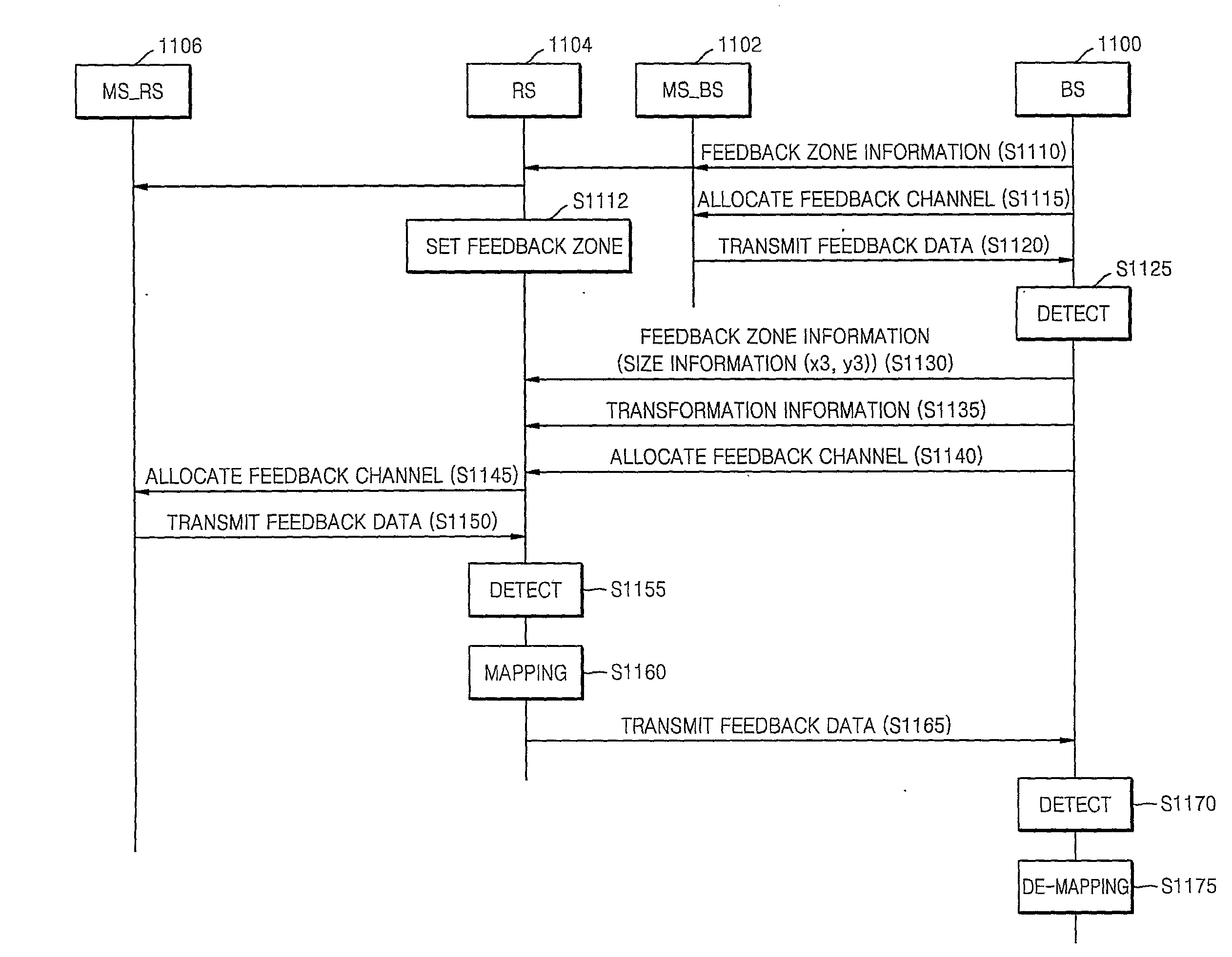
[0019]The present invention provides a method of configuring a feedback zone which can transmit feedback data such as channel quality information in one frame without a delay in a Relay Station (RS).
[0020]The present invention also provides a recording medium having recorded thereon a framestructure including a feedback zone which can transmit feedback data in one frame without a delay in a RS.
Technical Solution
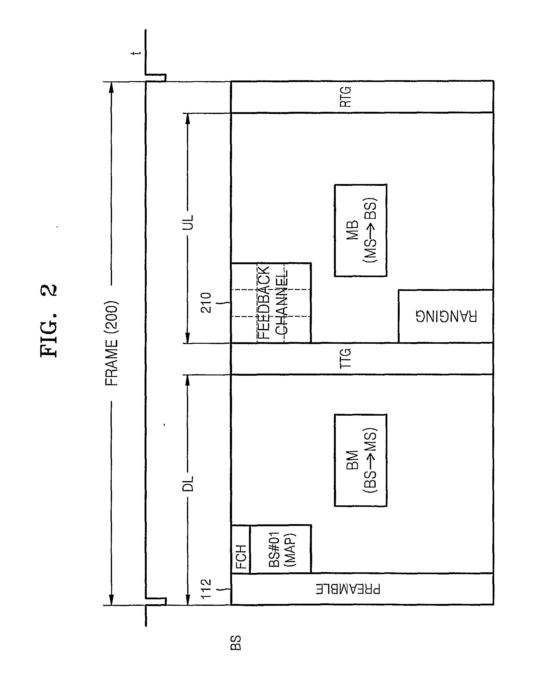
[0021]According to an aspect of the present invention, there is provided a method of configuring a feedback zone in a base station (BS), the method including the operations of allocating a first feedback zone in an access zone in which data is transmitted from a mobile station (MS) to the BS; and allocating a second feedback zone in a relay zone in which data is transmitted from a relay station (RS) to the BS, wherein the second feedback zone corresponds to the first feedback zone.
[0022]According to another aspect of the present invention, there is provided a...
PUM
 Abstract
Description
Claims
Application Information