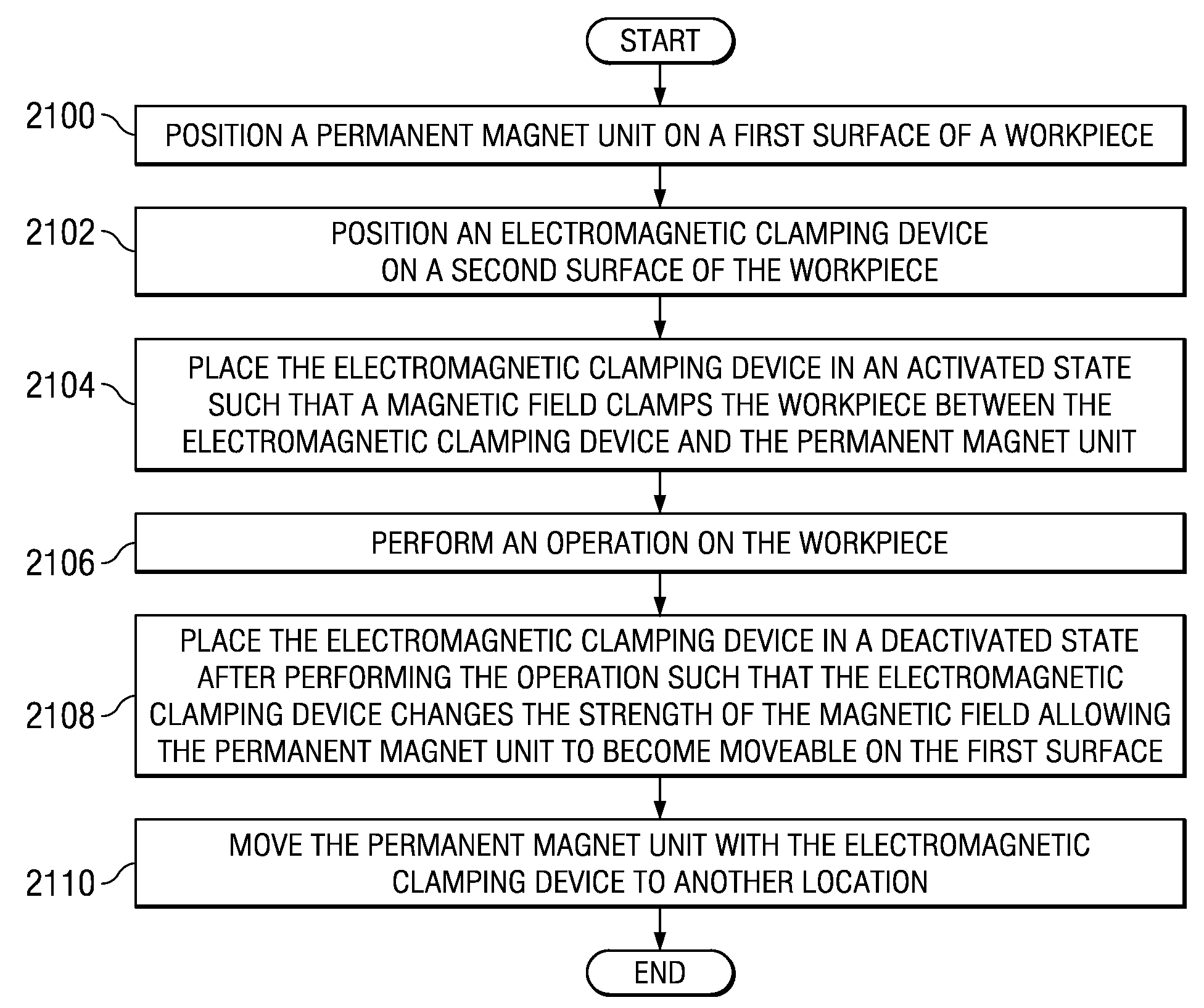
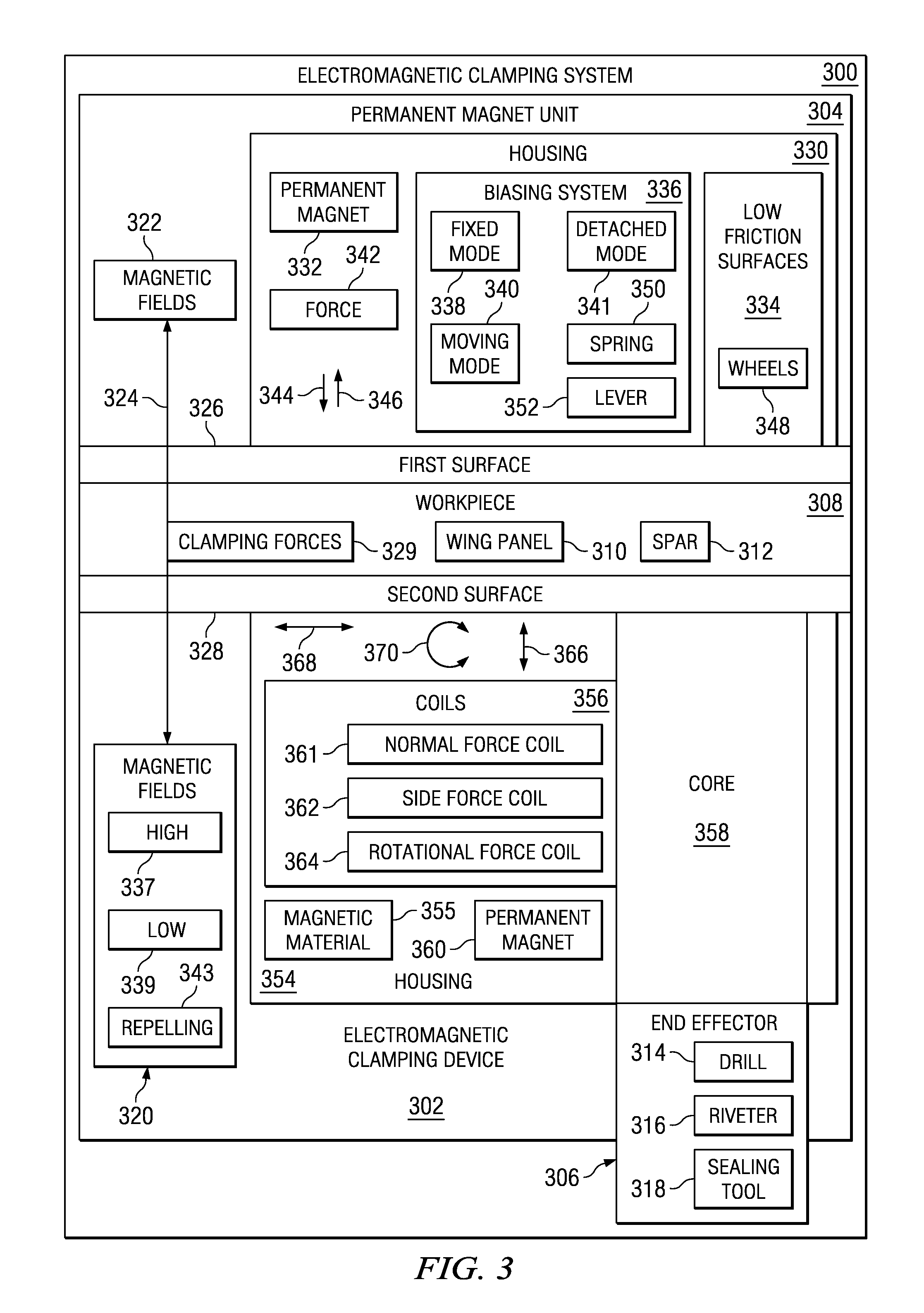
Electromagnetic clamping device
- Summary
- Abstract
- Description
- Claims
- Application Information
AI Technical Summary
Benefits of technology
Problems solved by technology
Method used
Image

Examples
Embodiment Construction
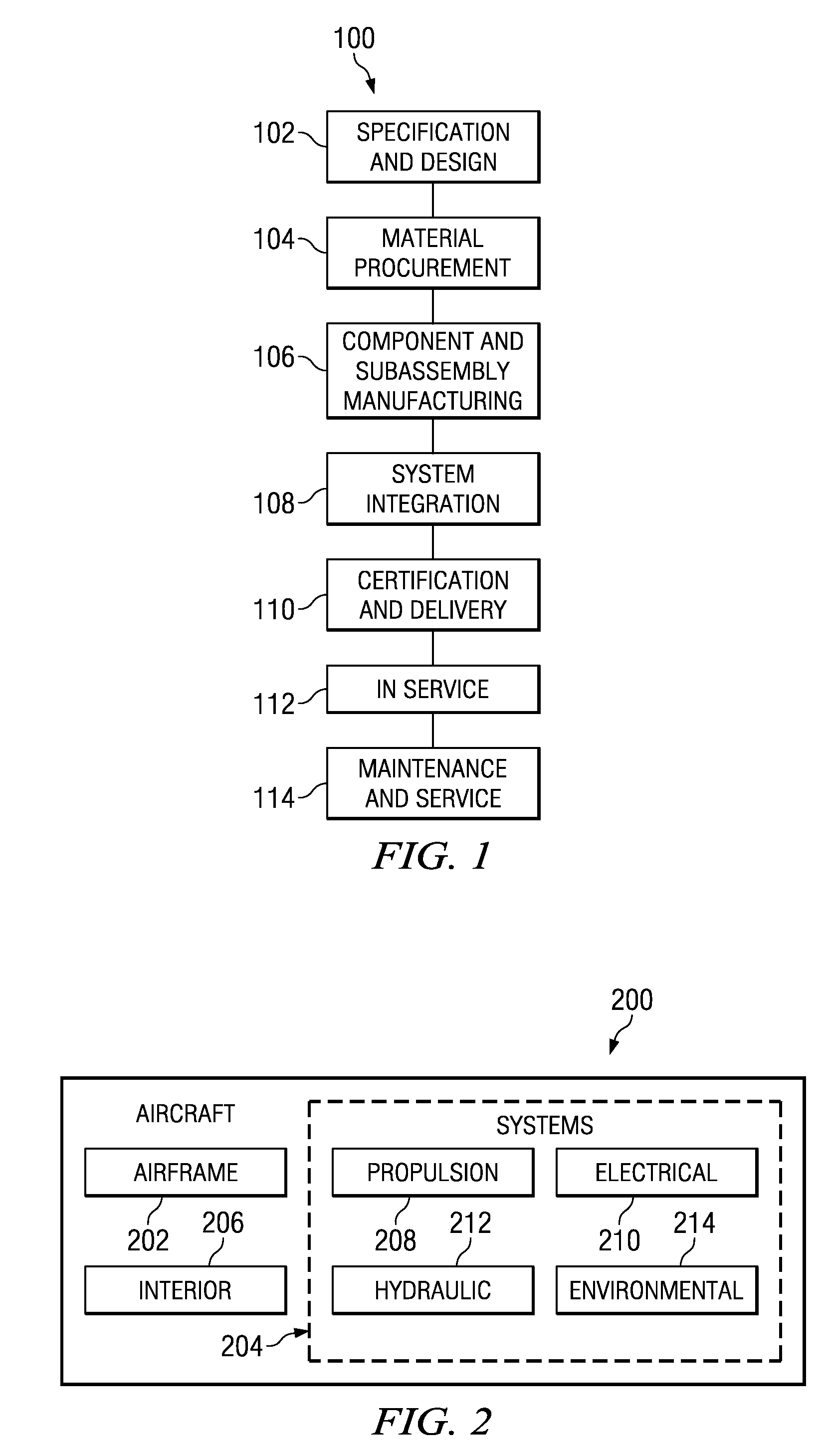
[0040]Referring more particularly to the drawings, embodiments of the disclosure may be described in the context of the aircraft manufacturing and service method 100 as shown in FIG. 1 and aircraft 200 as shown in FIG. 2. Turning first to FIG. 1, a diagram illustrating an aircraft manufacturing and service method is depicted in accordance with an advantageous embodiment. During pre-production, exemplary aircraft manufacturing and service method 100 may include specification and design 102 of aircraft 200 in FIG. 2 and material procurement 104.
[0041]During production, component and subassembly manufacturing 106 and system integration 108 of aircraft 200 in FIG. 2 takes place. Thereafter, aircraft 200 in FIG. 2 may go through certification and delivery 110 in order to be placed in service 112. While in service by a customer, aircraft 200 in FIG. 2 may be scheduled for routine maintenance and service 114, which may include modification, reconfiguration, refurbishment, and other mainten...
PUM
| Property | Measurement | Unit |
|---|---|---|
| Magnetic field | aaaaa | aaaaa |
| Strength | aaaaa | aaaaa |
| Friction | aaaaa | aaaaa |
Abstract
Description
Claims
Application Information
 - Generate Ideas
- Intellectual Property
- Life Sciences
- Materials
- Tech Scout
- Unparalleled Data Quality
- Higher Quality Content
- 60% Fewer Hallucinations
Browse by: Latest US Patents, China's latest patents, Technical Efficacy Thesaurus, Application Domain, Technology Topic, Popular Technical Reports.
© 2025 PatSnap. All rights reserved.Legal|Privacy policy|Modern Slavery Act Transparency Statement|Sitemap|About US| Contact US: help@patsnap.com