Filling system for hot filling of beverage bottles or containers in a bottle or container filling plant

a filling system and beverage bottle technology, applied in the directions of liquid handling, packaging goods, transportation and packaging, etc., can solve the problems of complex construction, high construction cost, time-consuming, etc., and achieve the effect of requiring and/or requiring a great deal of control effor

Inactive Publication Date: 2010-03-25
KHS GMBH
View PDF7 Cites 40 Cited by
  • Summary
  • Abstract
  • Description
  • Claims
  • Application Information

AI Technical Summary

Benefits of technology

[0009]This object is achieved through a filling system for filling a liquid product into bottles or similar containers. The filling system comprises at least one filler element with a product space or liquid channel realized in a filler element housing. The product space or liquid channel is in communication with a reservoir for the liquid product and on the underside of the filler element forming a liquid product discharge, via which the liquid product flows to the respective container to be filled retained on a container carrier. The filling system also comprises a liquid valve positioned in the liquid channel. To heat or keep the filler element warm during a hot-filling process, in the filler element housing, there is a first flow path, which connects a part section of the liquid channel, located with reference to the flow direction of the liquid product in the liquid channel upstream of the liquid valve, to a collecting channel that is common to a plurality of filler elements. At least one control valve is provided for controlling the flow of a hot liquid product from the reservoir through the part section and the first flow path into the first collecting channel.
[0010]For example, in filling intervals or in interruptions in the filling process, the filler elements are heated by the hot liquid product, which flows through the filler elements with the liquid valves closed in a first flow path that is realized in each filler element, said flow path in one po

Problems solved by technology

This machine concept is theoretically satisfactory, although it is complex, expensive an

Method used


Image

  • Filling system for hot filling of beverage bottles or containers in a bottle or container filling plant
  • Filling system for hot filling of beverage bottles or containers in a bottle or container filling plant
  • Filling system for hot filling of beverage bottles or containers in a bottle or container filling plant

Examples


Embodiment Construction

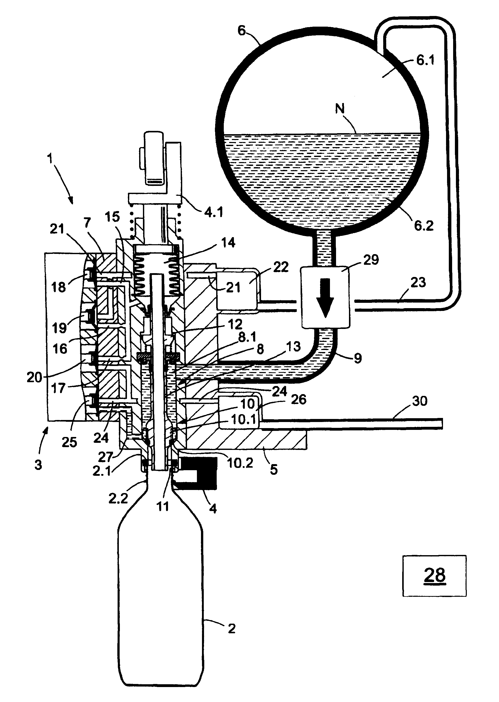
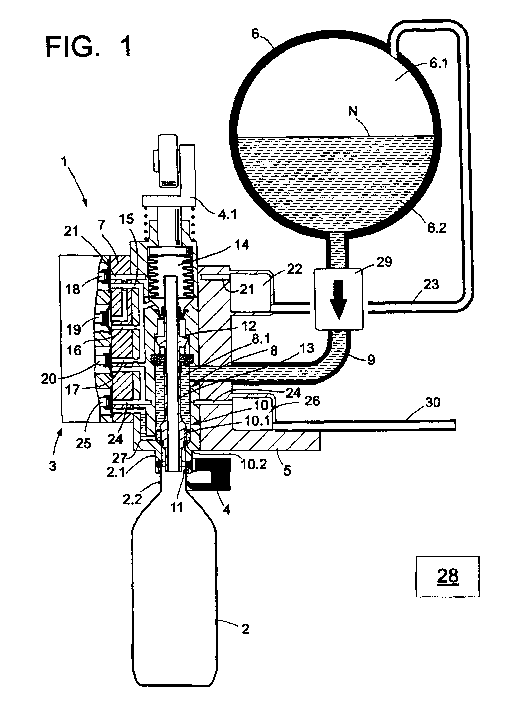
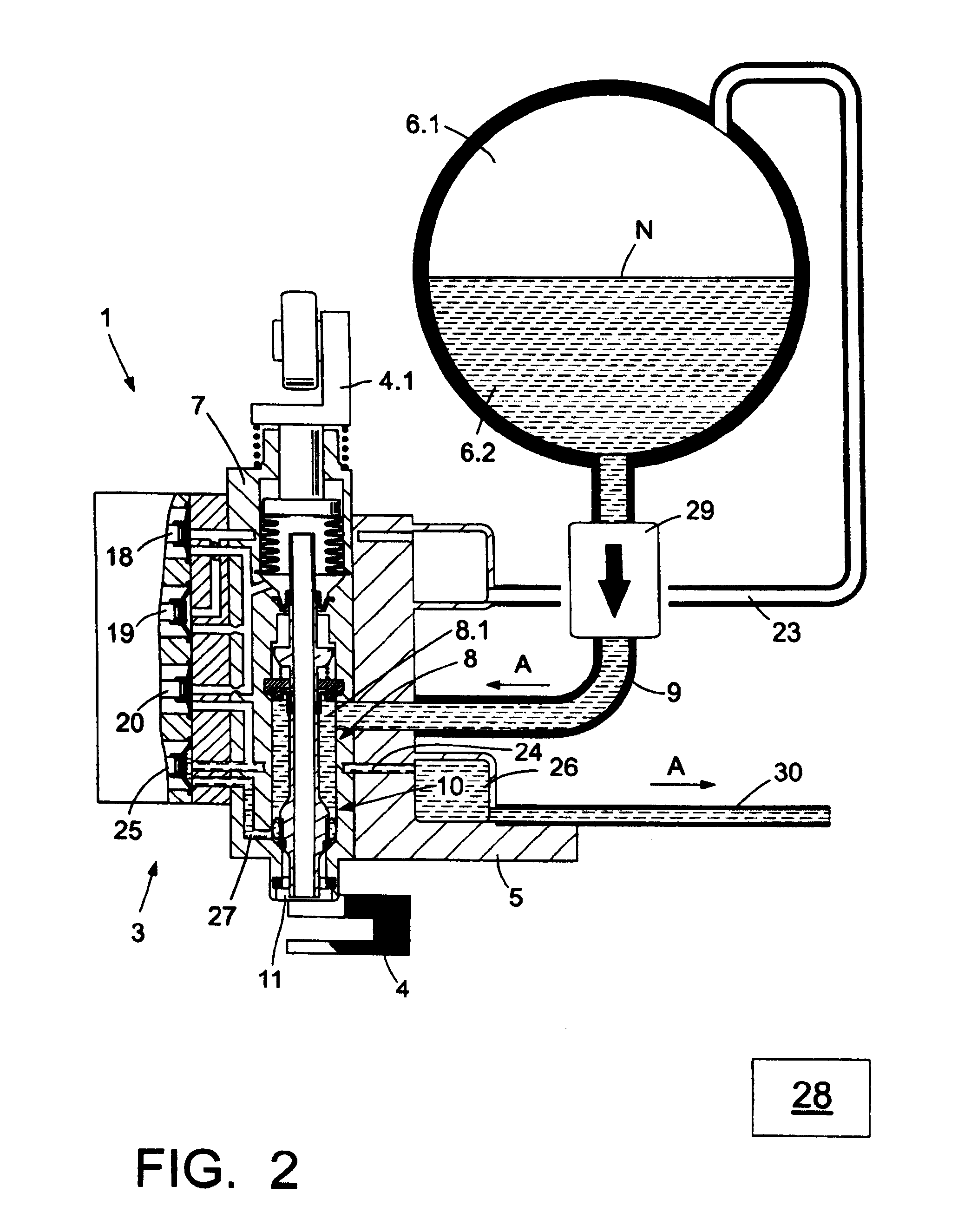
[0020]The filling system, identified in general in FIGS. 1 and 2 by the reference 1, is a component of a filling machine of the rotary type for filling a liquid product into bottles 2 or similar containers. The filling system 1, for this purpose, essentially comprises a filler element 3 and a bottle or container carrier 4 that is associated with said filler element, said bottle or container carrier, in the possible embodiment represented, serving to hold the bottle 2 at a mouth flange 2.2 that is formed below the bottle mouth 2.1 and, for this purpose, being realized, for example, in the manner of a fork. The filler element 3 and the associated container carrier 4 are provided with a plurality of identical-type filler elements 3 and container carriers 4 at the periphery of a rotor 5 that is rotatingly driveable about a vertical machine axis. A reservoir 6 that is common to the filler elements is situated at the rotor 5 above the filler elements 3, said reservoir being realized, for ...


PUM

PropertyMeasurementUnit
Flow rateaaaaaaaaaa
Volumeaaaaaaaaaa
Perimeteraaaaaaaaaa

Abstract

A filling system for hot filling of beverage bottles or containers in a bottle or container filling plant. The abstract of the disclosure is submitted herewith as required by 37 C.F.R. §1.72(b). As stated in 37 C.F.R. §1.72(b): A brief abstract of the technical disclosure in the specification must commence on a separate sheet, preferably following the claims, under the heading “Abstract of the Disclosure.” The purpose of the abstract is to enable the Patent and Trademark Office and the public generally to determine quickly from a cursory inspection the nature and gist of the technical disclosure. The abstract shall not be used for interpreting the scope of the claims. Therefore, any statements made relating to the abstract are not intended to limit the claims in any manner and should not be interpreted as limiting the claims in any manner.

Description

CONTINUING APPLICATION DATA[0001]This application is a Continuation-In-Part application of International Patent Application No. PCT / EP2008 / 002013, filed on Mar. 13, 2008, which claims priority from Federal Republic of Germany Patent Application No. 10 2007 014 702.5, filed on Mar. 23, 2007. International Patent Application No. PCT / EP2008 / 002013 was pending as of the filing date of this application. The United States was an elected state in International Patent Application No. PCT / EP2008 / 002013.[0002]This application is also a Continuation-In-Part application of International Patent Application No. PCT / 2008 / 001906, filed on Mar. 11, 2008, which claims priority from Federal Republic of Germany Patent Application No. 10 2007 014 701.7, filed on Mar. 23, 2007. International Patent Application No. PCT / 2008 / 001906 was pending as of the filing date of this application. The United States was an elected state in International Patent Application No. PCT / 2008 / 001906.BACKGROUND[0003]1. Technica...

Claims


Application Information

Patent Timeline
IPC IPC(8): B65B31/00B65B3/00
CPCB65B39/001B67C3/286B67C3/045B65B39/04B67C3/06
Inventor CLUSSERATH, LUDWIGKRULITSCH, DIETER-RUDOLF
Owner KHS GMBH
Why Eureka
Try Eureka