Integrated locking control and status indicator for manually operated railway switch stand

a technology of locking control and status indicator, which is applied in the direction of railway signalling, railway signalling and safety, mechanical devices for scotch-blocks, etc., and can solve the problem that the handle cannot be disengaged until

Inactive Publication Date: 2010-03-25
VAE NORTRAK NORTH AMERICA INC
View PDF29 Cites 8 Cited by
  • Summary
  • Abstract
  • Description
  • Claims
  • Application Information

AI Technical Summary

Benefits of technology

[0013]In particular, it is an object of the invention to provide a simple means to secure a switch stand and to obtain constant indications of the status of the switch stand and of the associated switch.

Problems solved by technology

The lock handle must be physically disengaged (unlocked) before the switch points can be moved, but the handle cannot be disengaged until the key is turned.
Further, once the key is inserted properly it is retained within the device and can only be removed once the locking handle has been returned to an engaged (locked) position, presumably after the switch points have been moved to the desired position.

Method used


Image

  • Integrated locking control and status indicator for manually operated  railway switch stand
  • Integrated locking control and status indicator for manually operated  railway switch stand
  • Integrated locking control and status indicator for manually operated  railway switch stand

Examples


Embodiment Construction

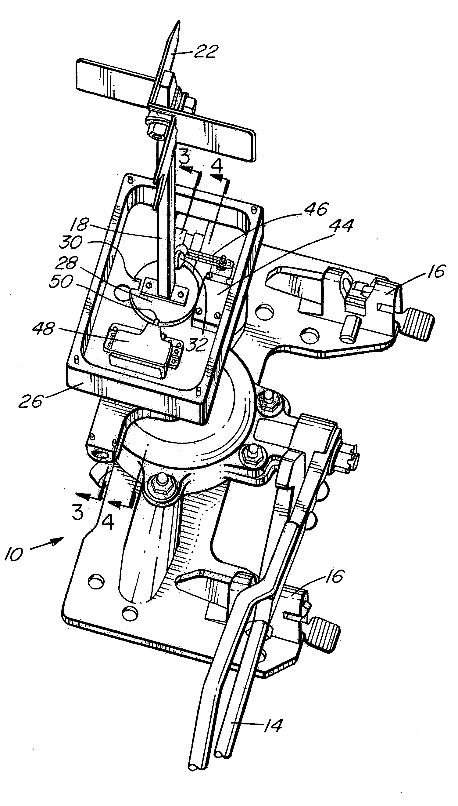
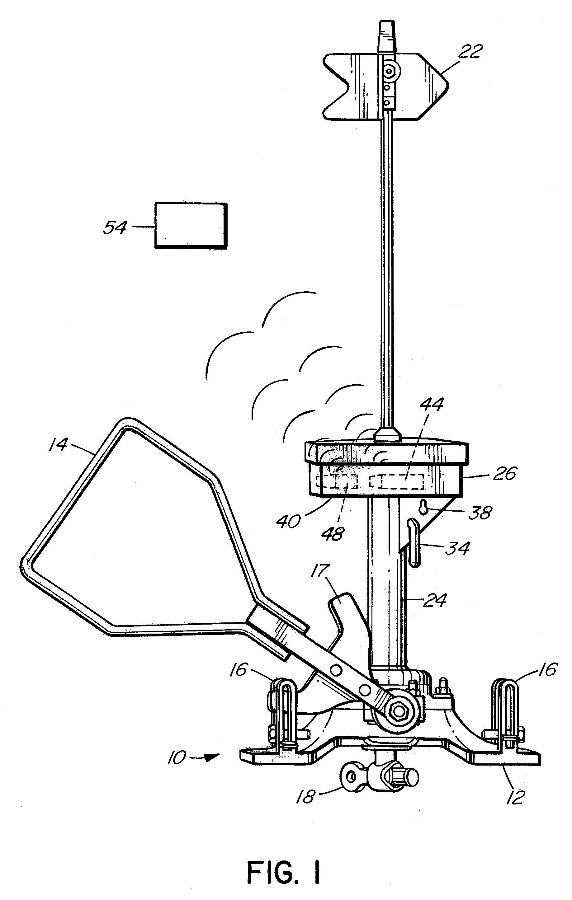
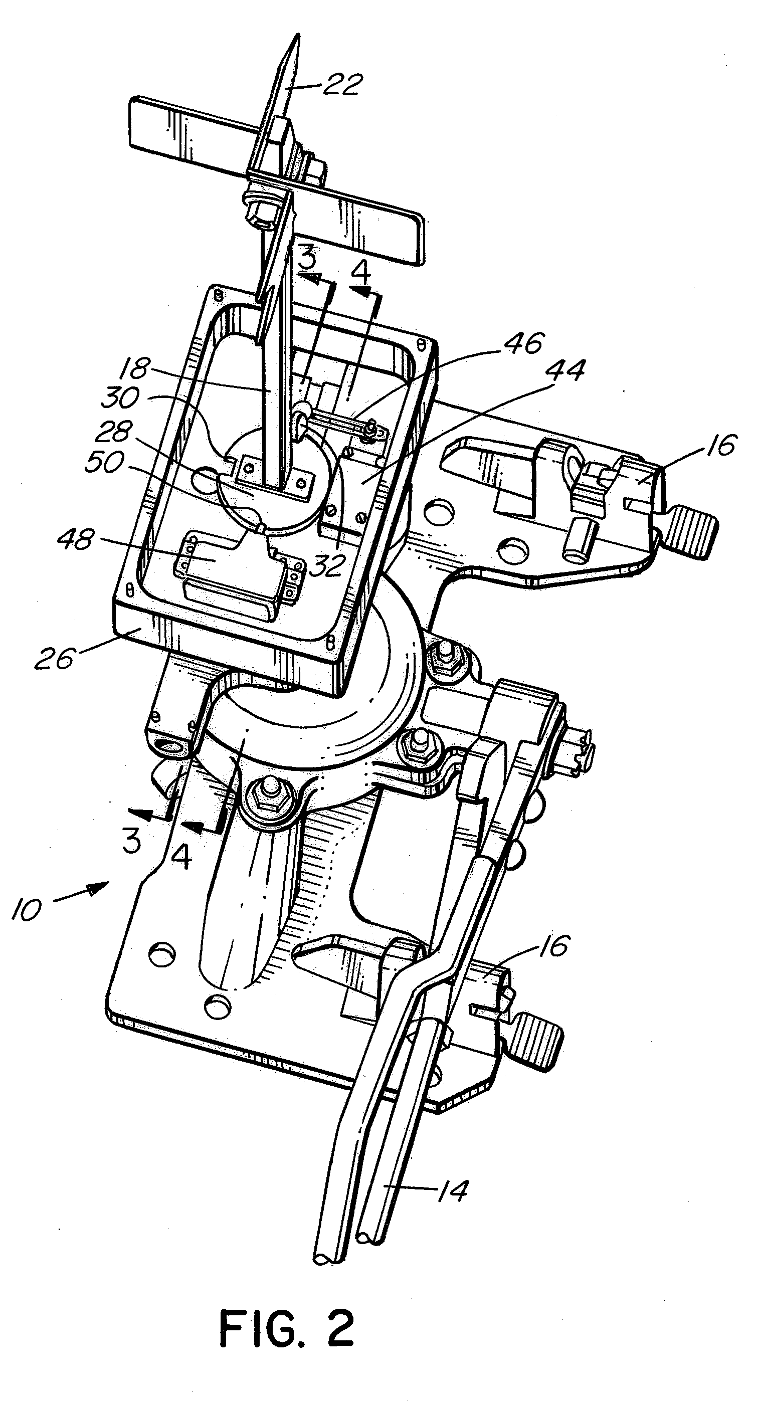
[0041]Referring to FIG. 1, the switch stand 10 is preferably a manual stand comprising a base 12 supporting a lever or throw handle 14 which moves between normal and reverse positions and may be secured in those positions by foot latches 16. FIG. 1 illustrates the throw handle 14 having a yoke 17 to interact with the foot latch 16, but it will be understood that any throw handle 14 of suitable configuration may be used, and in particular that the throw handle 14 need not have any yoke 17, but if a yoke is present, it may be of any suitable configuration. In addition, a secondary locking method, such as a padlock (not shown) may be used to secure the throw handle 14 to one of the foot latches 16, as is known in the art. The actuation of the throw handle 14 causes a vertical, elongated spindle 18 to rotate, moving the appropriate rods, such as throw rods, and throwing the associated switch points (not shown). Rotation of the spindle 18 also moves the mounted flag or target 22 to an ap...


PUM


Abstract

The invention relates to a device to be integrated with to a manual switch stand, particularly for use in dark territory. The device secures the spindle of the switch stand against rotation, thereby preventing authorized throwing of the switches. The device also contains sensors that will clearly indicate to an external observer both the position of the switch points and the locked or unlocked status of the switch stand. A particular sequence of steps must be taken before an operator will be able to unlock the switch stand and throw the switch, and further steps are required before he can secure the switch stand and remove his key. The switch stand must therefore be left in a locked state, and it continuously indicates the status of the switch stand to a remote monitor.

Description

FIELD OF THE INVENTION[0001]This invention relates to a mechanism to provide a definite indication of the position of the switch controlled by a switch stand and to secure the stand against unauthorized switching, and is particularly applicable for stands used in dark territory.BACKGROUND OF THE INVENTION[0002]A railroad switch includes moveable switch points (sometimes called blades) that direct the wheels onto the appropriate track. The switch points are driven from a first position, to direct the train onto one track, to a second position, to direct the train onto another track, by a power operated switch machine, or by a manually operated switch stand. The points are locked in one position until required to be switched back to the other position. Rail terminology commonly refers to the switch point position for the track most frequently used as the “normal” position, and the position for the track less frequently used as the “reverse” position.[0003]A power operated switch machi...

Claims


Application Information

Patent Timeline
Patent Type & Authority Applications(United States)
IPC IPC(8): B61L5/00
CPCB61L5/10B61L5/02
Inventor CLICK, GARYDUFFNER, BRENTSMITH, BRADLEYOUELETTE, KENNETH
Owner VAE NORTRAK NORTH AMERICA INC
Why Eureka
Try Eureka