Actuator for operating valves such as diaphragm valves

Active Publication Date: 2010-03-25
RICHARDS INDS
View PDF17 Cites 30 Cited by
  • Summary
  • Abstract
  • Description
  • Claims
  • Application Information

AI Technical Summary

Benefits of technology

[0007]It is an object of the present invention to provide a valve actuator that overcomes or mitig

Problems solved by technology

Because of the commercial importance of being able to retrofit actuators to older valves, the design of the valve flange has not evolved over the years.
However, since only two different orientations are possible, often neither orientation is ideal, given the space constraints in the installations.
However, these take up more space than may be convenient in some ins

Method used


Image

  • Actuator for operating valves such as diaphragm valves
  • Actuator for operating valves such as diaphragm valves
  • Actuator for operating valves such as diaphragm valves

Examples


Example

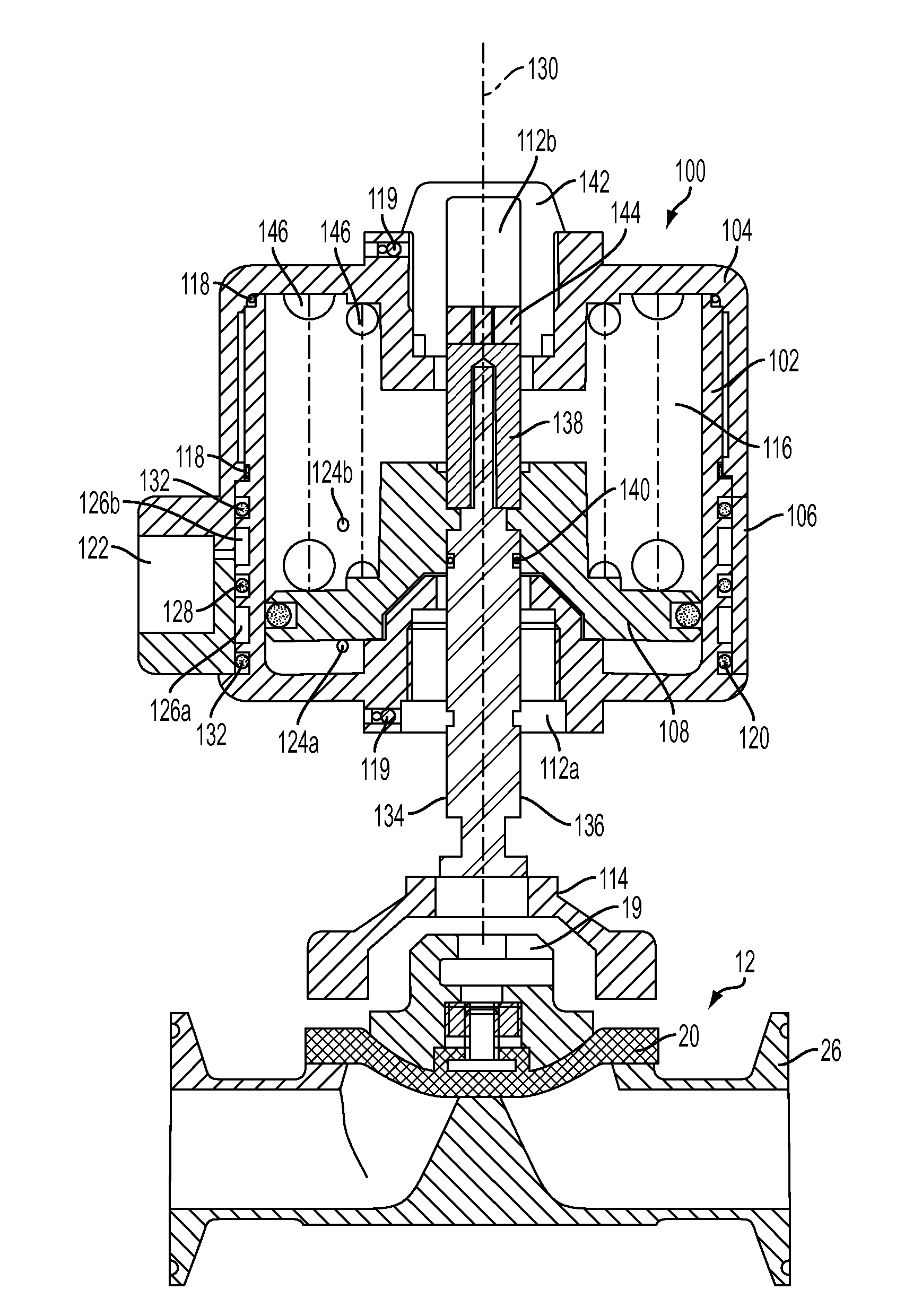
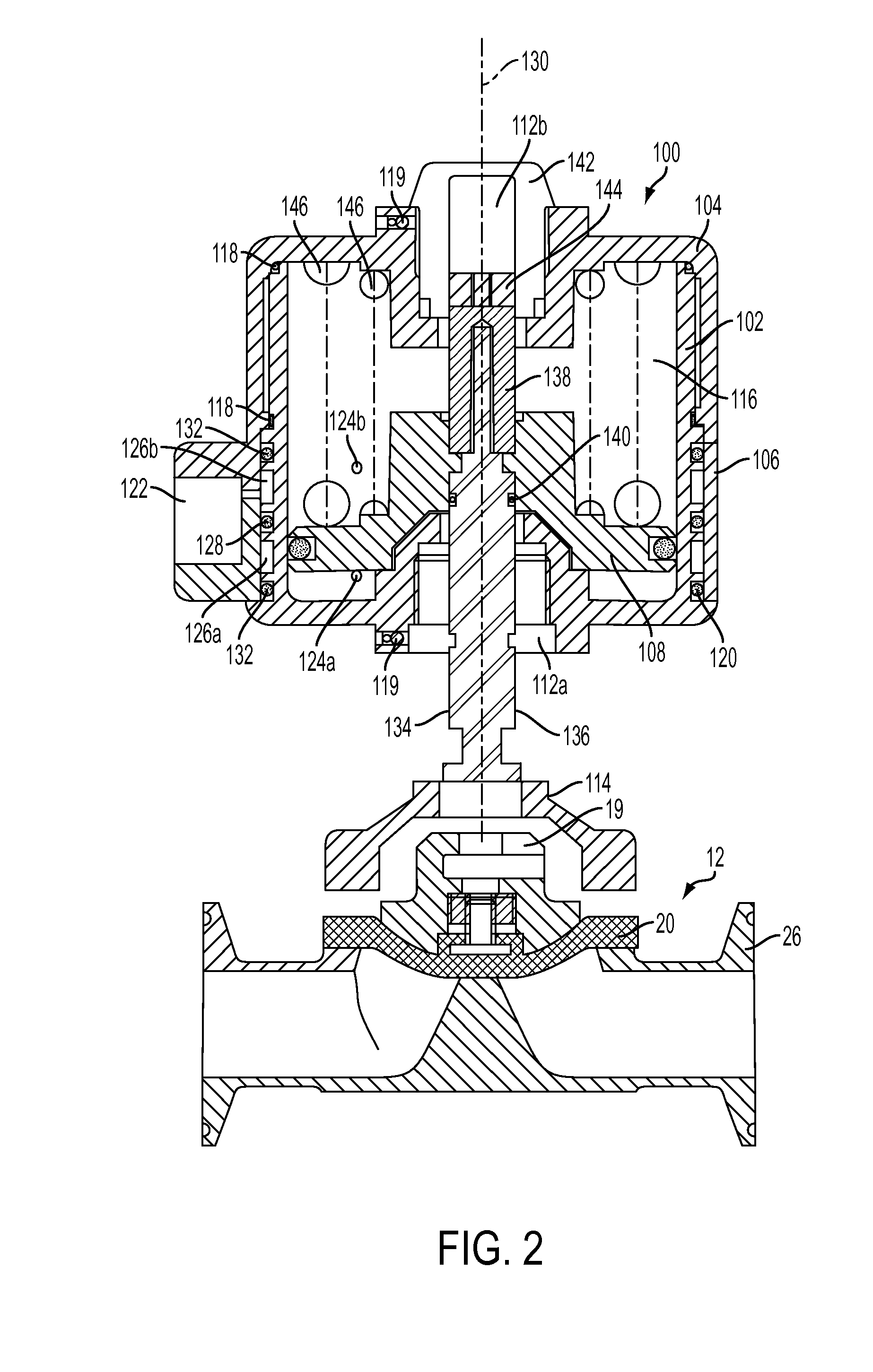
[0030]Referring first to FIGS. 2 and 3, an actuator 100 that is designed to operate a diaphragm valve 12 is shown. The actuator is made of a housing 102, a cap 104, a swivel ring 106 and a piston 108. The housing 102 has a cylindrical shape, open at one end and substantially closed at the other end. The substantially closed end is equipped with a connecting interface 112a that is designed to connect the actuator 100 to the valve 12, either directly or, as is the case in the present example, through the use of a bonnet 114. The housing may be made of different materials such as metals or plastics.

[0031]The cap 104 substantially covers the open end of the housing 102. It may also cover a first portion of the exterior of the housing 102. The cap 104 and the housing 102 define a substantially enclosed space 116 inside the housing 102. The cap 104 is sealed against the housing 102 with the use of cap O-rings 118 to prevent air from leaking out of the actuator 100.

[0032]Optionally, the ca...


PUM


Abstract

An actuator for operating a valve comprises a housing, a cap, a ring and a piston. The housing has a connecting interface for being mounted on the valve. The cap substantially covers a first portion of the housing. Both the cap and the housing define a substantially enclosed space inside the housing. The ring sealably covers a second portion of the housing. The ring is equipped with two ports that are in fluid communication with the enclosed space. The piston is slidably located inside the housing. Advantageously, an actuator assembly may include the actuator as previously described and one bonnet, one of the connecting interfaces of the actuator being connected to the bonnet. The bonnet is adapted to be mounted to a valve body.

Description

FIELD OF THE INVENTION[0001]The present invention generally relates to the field of fluid regulating devices. More particularly, the present invention relates to linear actuators for valves such as diaphragm valves.BACKGROUND OF THE INVENTION[0002]A conventional actuator 10 for a diaphragm valve is depicted in FIG. 1. In a typical fashion, a piston 14 connected to a stem 16 moves up and down within an actuator housing 18. The stem 16 is, directly or through the use of an adaptor 19, in contact with a diaphragm 20, which closes or opens the valve 12 according to the piston position. The piston 14 is biased to a normal position by the force of a spring 22. When a pressurized fluid such as air is introduced on the side of the piston opposed to the spring 22, the piston 14 moves under the air pressure, which pulls on the diaphragm 20, either opening the valve 12 as in the case of the valve shown in FIG. 1, or closing the valve. When the air pressure is released, the spring 22 returns th...

Claims


Application Information

Patent Timeline
IPC IPC(8): F16K1/00
CPCF16K31/1221F16K27/0281Y10T137/5196Y10T137/5283
Inventor LACASSE, LOUISBALASUBRAMANIAN, DAVID
Owner RICHARDS INDS
Why Eureka
Try Eureka