
Touch sensor device

Inactive Publication Date: 2010-03-25
ATLAB INC
View PDF10 Cites 4 Cited by
  • Summary
  • Abstract
  • Description
  • Claims
  • Application Information

AI Technical Summary

Benefits of technology

[0028]The touch sensor device of the present invention connects an external touch sensor device and a light-emitting device to each input / output (I / O) terminal in common and controls each of them. Therefore, it is possible to reduce the number of I / O terminals, thus reducing production cost. In addition, it is possible to manufacture small sized touch sensor devices, thus enabling the miniaturization of portable electronic devices.

Problems solved by technology

However, since the number of I / O terminals of the touch sensor device 101 is limited, the numbers of external contact pads and light-emitting devices that can be connected to the I / O terminals also are limited.

Method used


Image

  • Touch sensor device
  • Touch sensor device
  • Touch sensor device

Examples


Embodiment Construction

[0033]Hereinafter, exemplary embodiments of the present invention will be described in detail. However, the present invention is not limited to the exemplary embodiments disclosed below, but can be implemented in various forms. The following exemplary embodiments are described in order to enable those of ordinary skill in the art to embody and practice the invention.

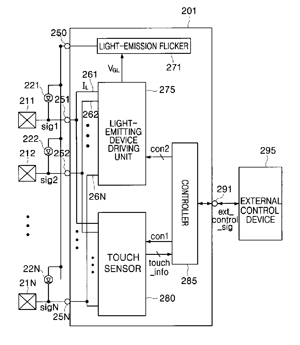
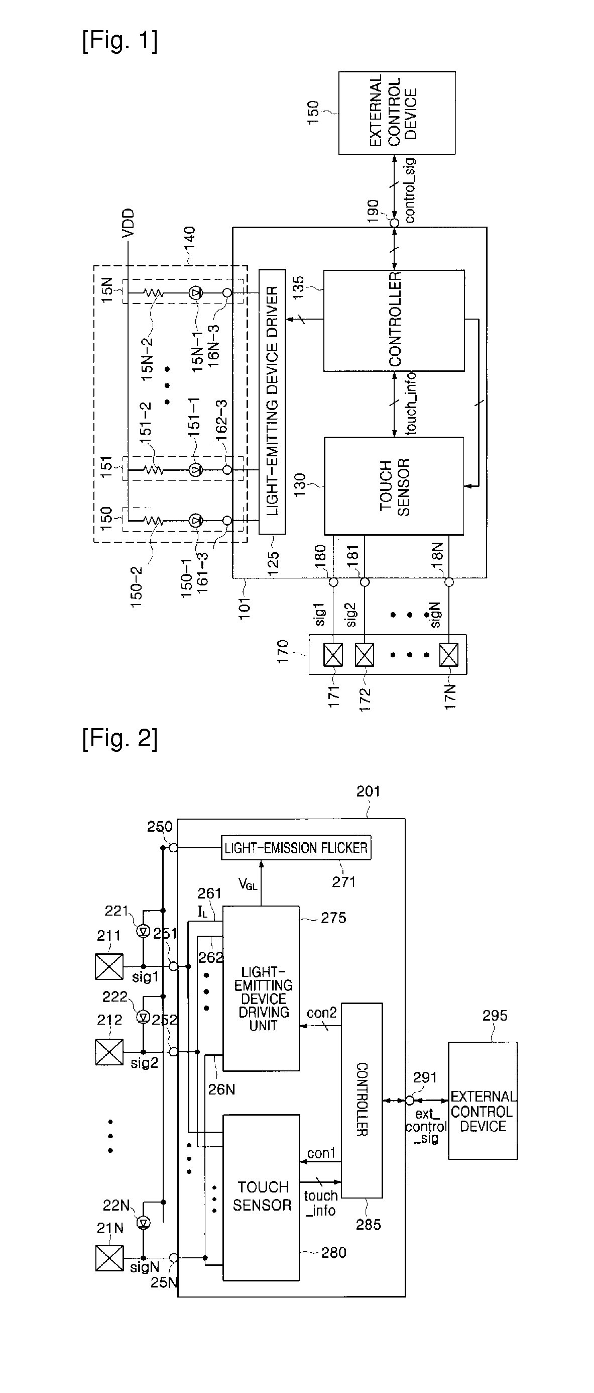
[0034]FIG. 2 is a block diagram showing a configuration of a touch sensor device according to an exemplary embodiment of the present invention.

[0035]A touch sensor and light-emission controller unit includes a light-emission flicker 271, a light-emitting device driving unit 275, a touch sensor 280, and a controller 285. Here, N is an arbitrary natural number. Contact pads 211 to 21N and light emitting diodes (LEDs) 221 to 22N, which are light-emitting units, are commonly connected to a plurality of input / output (I / O) terminals 251 to 25N, respectively. And, the plurality of input / output (I / O) terminals 251 to 25N are con...


PUM


Abstract

Provided is a touch sensor device including: at least one terminal connected to at least one contact pad; at least one common terminal; at least one light emitter connected between the common terminal and the terminal; and a touch sensor and light-emission controller unit connected to the common terminal and the terminal, and when a touch is sensed by the contact pad, controlling a corresponding light emitter to emit light.

Description

TECHNICAL FIELD[0001]The present invention relates to a touch sensor device, and more particularly, to a touch sensor device having a reduced number of input / output (I / O) terminals.BACKGROUND ART[0002]A general touch sensor device has a plurality of separate input / output (I / O) terminals for receiving an input generated by external touch, driving an externally arranged light-emitting device such as a light emitting diode (LED), and communicating to external control device[0003]FIG. 1 is a block diagram showing a configuration of a conventional touch sensor device.[0004]A touch sensor device 101 comprises a light-emitting device driver 125, a touch sensor 130, and a controller 135. In addition, the touch sensor device further comprises a plurality of output terminals 161-3 to 16N-3 for outputting a signal to external light-emitting devices 150 to 15N, and a plurality of I / O terminals 181 to 18N for receiving and outputting a signal from / to an external contact unit 170.[0005]The contac...

Claims


Application Information

Patent Timeline
IPC IPC(8): H05B37/02
CPCG06F3/0416G06F3/04164H04M1/22H04M2250/22
Inventor SHIN, YOUNG-HOLEE, BANG-WONSHIN, DU-SU
Owner ATLAB INC
Learn More