Anisotropic optical cover for touch panel display

a touch panel display and optical cover technology, applied in the field of touch panels, can solve the problems of affecting the clarity of a displayed image when transmitted through such materials, and the display device behind a touch sensor panel in the touch screen can present certain issues, so as to improve the detection of the touch panel according to embodiments of the invention, and improve the detection of the touch panel

Inactive Publication Date: 2010-03-25
APPLE INC
View PDF22 Cites 21 Cited by
  • Summary
  • Abstract
  • Description
  • Claims
  • Application Information

AI Technical Summary

Benefits of technology

[0004]A touch panel display configured to improve touch panel detection for sensor panels embedded in display modules is disclosed. Touch panel detection according to embodiments of the invention can be improved by arranging an optically anisotropic cover over a display module within which an optical sensor panel is embedded.

Problems solved by technology

However, the positioning of a display device behind a touch sensor panel in a touch screen can present certain issues.
For example, although touch sensor panels are constructed of clear materials, the clarity of a displayed image can be negatively impacted when transmitted through such materials.

Method used


Image

  • Anisotropic optical cover for touch panel display
  • Anisotropic optical cover for touch panel display
  • Anisotropic optical cover for touch panel display

Examples


Embodiment Construction

[0016]In the following description of preferred embodiments, reference is made to the accompanying drawings where it is shown by way of illustration specific embodiments in which the invention can be practiced. It is to be understood that other embodiments can be used and structural changes can be made without departing from the scope of the embodiments of this invention.

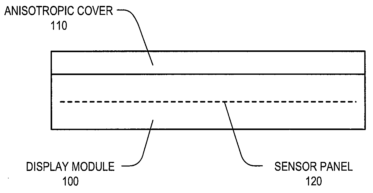
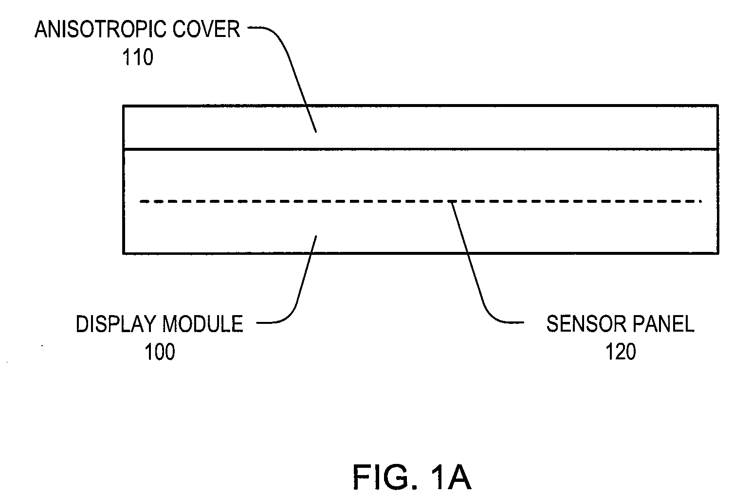
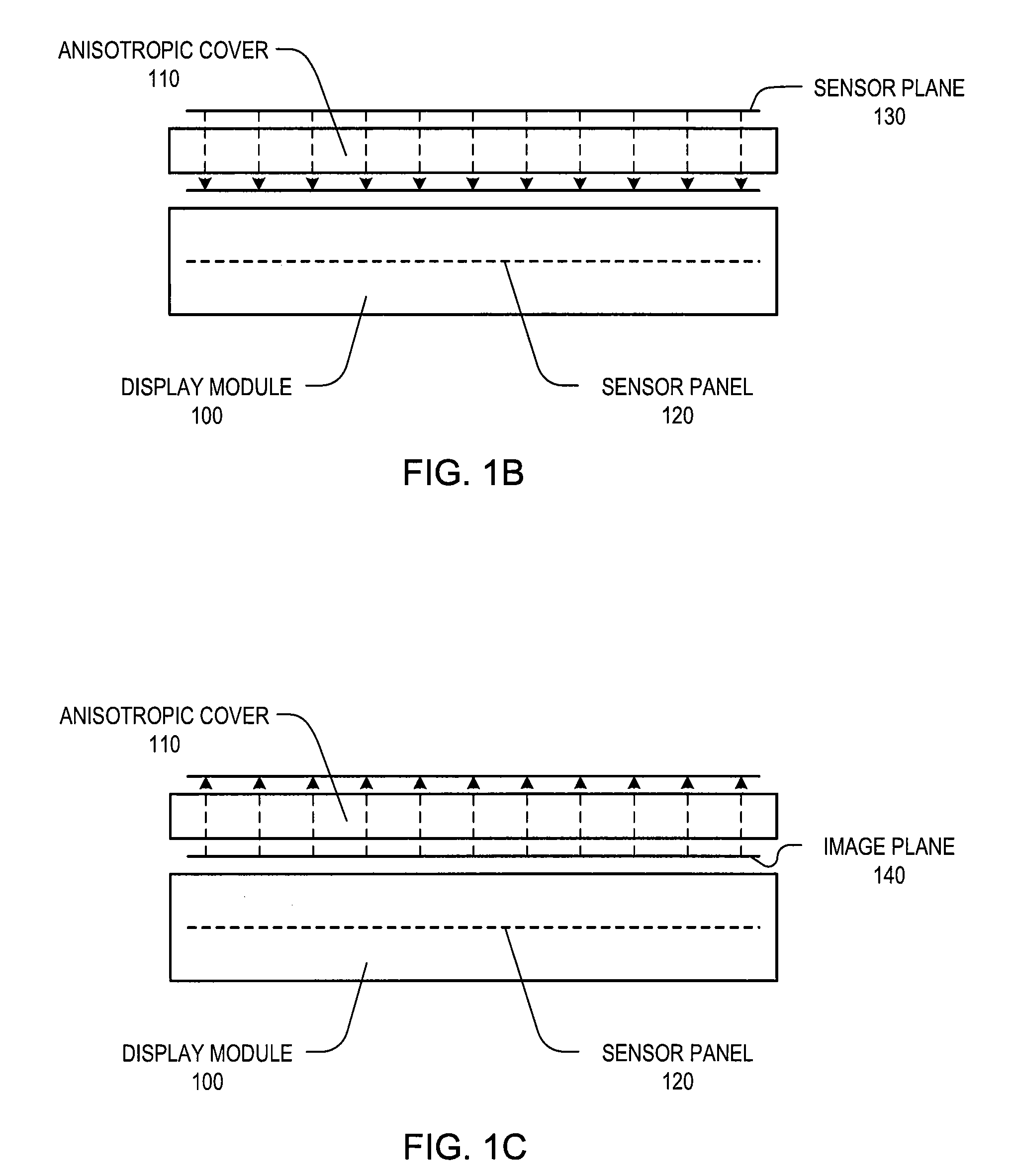
[0017]Embodiments of the invention relate to improving touch panel detection for sensor panels embedded in display modules. Touch panel detection can be improved by arranging an optically anisotropic cover over a display module within which an optical sensor panel is embedded. Since the optically anisotropic cover comprises light-guiding channels through which light is guided by total internal reflection, the cover can effectively shift the sensor plane from an outer surface of the cover, near the location of an object to be detected, to an inner surface of the cover, near the location of the sensor panel. In additi...


PUM

PropertyMeasurementUnit
anisotropicaaaaaaaaaa
total internal reflectionaaaaaaaaaa
areaaaaaaaaaaa

Abstract

A touch panel display configured to improve touch panel detection for sensor panels embedded in display modules. Touch panel detection can be improved by arranging an optically anisotropic cover over a display module within which an optical sensor panel is embedded. Since the optically anisotropic cover comprises light-guiding channels through which light is guided by total internal reflection, the cover can effectively shift the sensor plane from an outer surface of the cover, near the location of an object to be detected, to an inner surface of the cover, near the location of the sensor panel. In additional, the optically anisotropic cover can effectively shift the image plane from the inner surface of the cover, near the display module, to the outer surface of the cover, near the viewing surface.

Description

FIELD OF THE INVENTION [0001]This relates generally to touch panels used as input devices for computing systems, and more particularly, to improving touch panel detection for touch sensor panels embedded in display modules.BACKGROUND OF THE INVENTION [0002]Many types of input devices are presently available for performing operations in a computing system, such as buttons or keys, mice, trackballs, joysticks, touch sensor panels, touch screens and the like. Touch screens, in particular, are becoming increasingly popular because of their ease and versatility of operation as well as their declining price. Touch screens can include a touch sensor panel, which can be a clear panel with a touch-sensitive surface, and a display device such as a liquid crystal display (LCD) that can be positioned partially or fully behind the panel so that the touch-sensitive surface can cover at least a portion of the viewable area of the display device. Touch screens can allow a user to perform various fu...

Claims


Application Information

Patent Timeline
Patent Type & Authority Applications(United States)
IPC IPC(8): G06F3/042G02F1/1335
CPCG02F1/13338G06F3/042G06F3/0412
Inventor LYNCH, BRIANDINH, RICHARD HUNG MINHBERNSTEIN, JEFFREY TRAER
Owner APPLE INC
Why Eureka
Try Eureka