
Thin-Film Magnetic Head Having Microwave Magnetic Exciting Function And Magnetic Recording And Reproducing Apparatus

Inactive Publication Date: 2010-03-25
TDK CORPARATION
View PDF6 Cites 22 Cited by
  • Summary
  • Abstract
  • Description
  • Claims
  • Application Information

AI Technical Summary

Benefits of technology

[0018]It is therefore an object of the present invention to provide a thin-film magnetic head having microwave magnetic exciting function and a magnetic recording and reproducing apparatus with this thin-film magnetic head, whereby a data signal can be precisely written onto a magnetic recording medium having a large coercivity without heating the medium.
[0023]It is preferred that the thin-film magnetic head further includes a write head element with a perpendicular magnetic recording structure having a main pole, an auxiliary pole and a coil means wound to pass through between the main pole and the auxiliary pole, that the write magnetic field production means includes the coil means, and that the at least line conductor of the microwave radiator is arranged between the main pole and the auxiliary pole. In the write head element with a perpendicular magnetic recording structure, because the strongest write magnetic field is produced at the end edge of the tope end section of the main pole near the auxiliary pole, if the line conductor is arranged between the main pole and the auxiliary pole, the microwave band resonance magnetic field can be more effectively applied to the magnetic recording medium.
[0029]It is preferred that the thin-film magnetic head further includes a write head element with a perpendicular magnetic recording structure having a main pole, an auxiliary pole and a coil means wound to pass through between the main pole and the auxiliary pole, that the write magnetic field production means includes the coil means, and that the at least line conductor of the microwave radiator is arranged between the main pole and the auxiliary pole. In the write head element with a perpendicular magnetic recording structure, because the strongest write magnetic field is produced at the end edge of the tope end section of the main pole near the auxiliary pole, if the line conductor is arranged between the main pole and the auxiliary pole, the microwave band resonance magnetic field can be more effectively applied to the magnetic recording medium.

Problems solved by technology

This causes deterioration in a signal-to-noise ratio (S / N), and in the worst case, the signal detected by the read head element may disappear.
As aforementioned, due to the limit of recording ability of the write head element, high-density recording becomes difficult now.
However, there are various difficulties and problems in these TAMR techniques.
For example, (1) a structure of the thin-film magnetic head becomes extremely complicated and its manufacturing cost becomes expensive because the head has to have both a magnetic element and an optical element, (2) it is required to develop a magnetic recording layer with a coercivity Hc of high temperature-dependency, (3) adjacent track erase or unstable recording state may occur due to thermal demagnetization during the recording process.
However, according to the conventional technique, since the microwave magnetic field radiation means consists of a write coil wound around a magnetic body or of an individual sub-coil separately formed from the write coil, if a frequency of a microwave signal to be applied more increases, radiation of the microwave magnetic field will occur at a part of the write coil or the sub-coil itself and thus it is impossible to radiate microwave magnetic field toward the magnetic recording medium even when the power supply is increased.
Therefore, if the frequency of the microwave signal to be applied more increases, it is quite difficult to increase the anisotropy magnetic field Hk of the recording layer.

Method used


Image

  • Thin-Film Magnetic Head Having Microwave Magnetic Exciting Function And Magnetic Recording And Reproducing Apparatus
  • Thin-Film Magnetic Head Having Microwave Magnetic Exciting Function And Magnetic Recording And Reproducing Apparatus
  • Thin-Film Magnetic Head Having Microwave Magnetic Exciting Function And Magnetic Recording And Reproducing Apparatus

Examples


Embodiment Construction

[0047]Hereinafter, an embodiment according to the present invention will be described with reference to these appended drawings. In these drawings, the similar elements are indicated by using the same reference symbols, respectively. Also, in the drawings, dimensions in each element and between the elements are optional for easy understanding of the configuration.

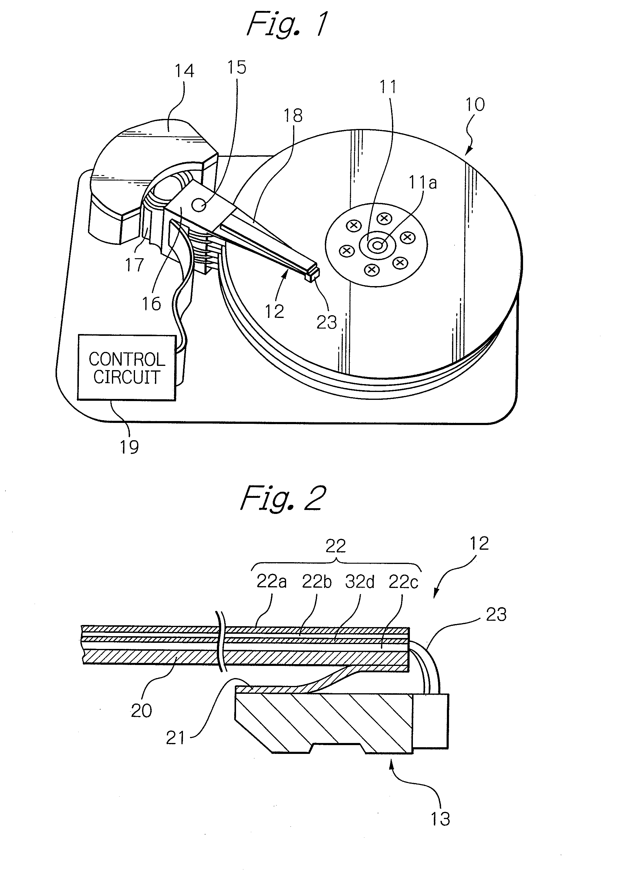
[0048]FIG. 1 schematically illustrates a main part structure of an embodiment of a magnetic recording and reproducing apparatus according to the present invention, and FIG. 2 schematically illustrates a part of an HGA in the magnetic recording and reproducing apparatus shown in FIG. 1.

[0049]In FIG. 1, which represents a magnetic disk drive apparatus as the embodiment of the magnetic recording and reproducing apparatus, reference numeral 10 denotes a plurality of magnetic disks capable of rotating about a rotary axis 11a of a spindle motor 11, 12 denotes the HGA for appropriately facing a thin-film magnetic head or a magneti...


PUM


Abstract

A thin-film magnetic head having microwave magnetic exciting function includes a write magnetic field production means for producing, in response to a write signal, a write magnetic field to be applied into a magnetic recording medium, and at least line conductor of a microwave radiator of a plane-structure type, formed independent from the write magnetic field production means, for radiating, by feeding there through a microwave excitation current, a microwave band resonance magnetic field with a frequency equal to or in a range near a ferromagnetic resonance frequency FR of the magnetic recording medium.

Description

PRIORITY CLAIM[0001]This application claims priority from Japanese patent application No. 2008-242400, filed on Sep. 22, 2008, which is incorporated herein by reference.BACKGROUND OF THE INVENTION[0002]1. Field of the Invention[0003]The present invention relates to a thin-film magnetic head having microwave magnetic exciting function for recording data signal onto a magnetic recording medium that has a large coercivity for thermally stabilizing the magnetization, and to a magnetic recording and reproducing apparatus with this thin-film magnetic head.[0004]2. Description of the Related Art[0005]With the demand for higher recording density of a magnetic recording and reproducing apparatus such as a magnetic disk drive apparatus, each bit cell in a magnetic recording medium for recording digital information has been miniaturized and, as a result, a signal detected by a read head element in the thin-film magnetic head sways due to such as thermal fluctuation. This causes deterioration i...

Claims


Application Information

Patent Timeline
IPC IPC(8): G11B5/02
CPCG11B5/1278G11B2005/0024G11B2005/001
Inventor IKEDA, HIROSHINOGUCHI, KIYOSHIKAJIHARA, SAORISATO, ISAMU
Owner TDK CORPARATION
Features
  • Generate Ideas
  • Intellectual Property
  • Life Sciences
  • Materials
  • Tech Scout
  • Unparalleled Data Quality
  • Higher Quality Content
  • 60% Fewer Hallucinations
Learn More