
Magnetic recording and reproducing apparatus with thin-film magnetic head having microwave magnetic exciting function

a technology of magnetic recording and reproducing apparatus, which is applied in special recording techniques, instruments, nanoinformatics, etc., can solve the problems of deterioration of signal-to-noise ratio (s/n), signal detected by the read head element may disappear, and high-density recording becomes difficult now

Inactive Publication Date: 2012-05-22
TDK CORPARATION
View PDF7 Cites 0 Cited by
  • Summary
  • Abstract
  • Description
  • Claims
  • Application Information

AI Technical Summary

Benefits of technology

This solution prevents standing waves and energy absorption within the apparatus, enabling precise data writing on high coercivity media without thermal assistance, simplifying the head structure, and reducing manufacturing costs while maintaining high recording density.

Problems solved by technology

This causes deterioration in a signal-to-noise ratio (S / N), and in the worst case, the signal detected by the read head element may disappear.
As aforementioned, due to the limit of recording ability of the write head element, high-density recording becomes difficult now.
However, there are various difficulties and problems in these TAMR techniques.
For example, (1) a structure of the thin-film magnetic head becomes extremely complicated and its manufacturing cost becomes expensive because the head has to have both a magnetic element and an optical element, (2) it is required to develop a magnetic recording layer with a coercivity Hc of high temperature-dependency, (3) adjacent track erase or unstable recording state may occur due to thermal demagnetization during the recording process.
Due to the peaks and valleys of the standing wave, it is impossible to keep the electrical potential on the magnetic recording medium constant.
Also, if a frequency resonance occurs at a part of the housing depending upon the dimension of space, partial absorption of energy may occur causing the microwave excitation energy to become unstable.

Method used


Image

  • Magnetic recording and reproducing apparatus with thin-film magnetic head having microwave magnetic exciting function
  • Magnetic recording and reproducing apparatus with thin-film magnetic head having microwave magnetic exciting function
  • Magnetic recording and reproducing apparatus with thin-film magnetic head having microwave magnetic exciting function

Examples


Embodiment Construction

[0040]Hereinafter, an embodiment according to the present invention will be described with reference to these appended drawings. In these drawings, the similar elements are indicated by using the same reference symbols, respectively. Also, in the drawings, dimensions in each element and between the elements are optional for easy understanding of the configuration.

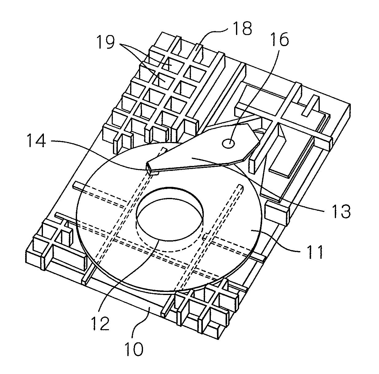
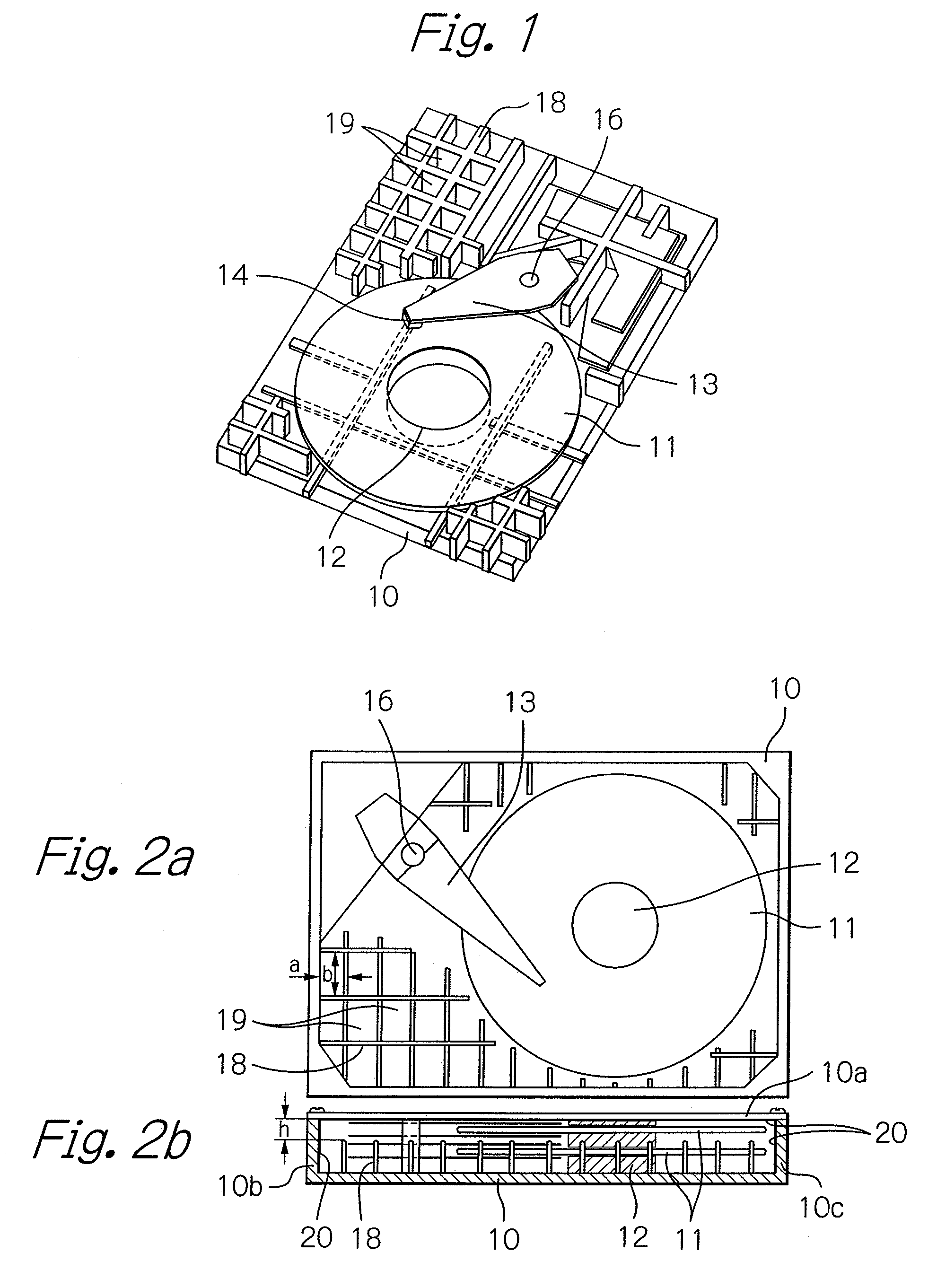
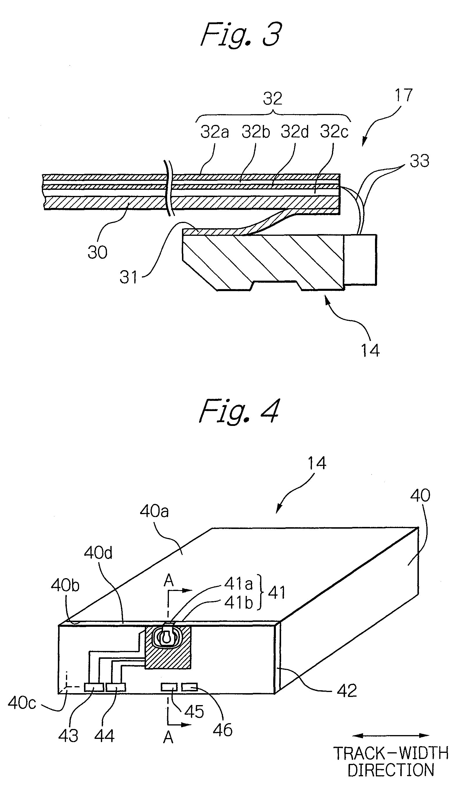
[0041]FIG. 1 schematically illustrates a partially omitted main part of a magnetic disk drive apparatus as an embodiment of a magnetic recording and reproducing apparatus according to the present invention, FIGS. 2a and 2b schematically illustrate a main part of the magnetic disk drive apparatus shown in FIG. 1, and FIG. 3 schematically illustrates a part of an HGA in the magnetic disk drive apparatus shown in FIGS. 1, 2a and 2b.

[0042]In FIGS. 1, 2a and 2b, which represent the magnetic disk drive apparatus as the embodiment of a magnetic recording apparatus, reference numeral 10 denotes a metal housing that accommodates th...


PUM

PropertyMeasurementUnit
widthaaaaaaaaaa
ferromagnetic resonance frequencyaaaaaaaaaa
thicknessaaaaaaaaaa

Abstract

A magnetic recording and reproducing apparatus includes a metal housing, a magnetic recording medium having a magnetic recording layer, and a thin-film magnetic head having a write magnetic field production unit and a resonance magnetic field production unit. The apparatus further includes a write signal generation unit for generating the write signal, a microwave signal generation unit for generating the microwave excitation signal, a transmission unit for feeding the microwave excitation signal to the resonance magnetic field production unit and for feeding the write signal to the write magnetic field production unit, and a plurality of metal ribs, arranged in the metal housing, for forming a plurality of cavities. Each of the plurality of cavities having a rectangular horizontal section shape and having dimensions to produce no resonance at a frequency of the microwave excitation signal.

Description

PRIORITY CLAIM[0001]This application claims priority from Japanese patent application No. 2008-136607, filed on May 26, 2008, which is incorporated herein by reference.BACKGROUND OF THE INVENTION[0002]1. Field of the Invention[0003]The present invention relates to a magnetic recording and reproducing apparatus with a thin-film magnetic head having microwave magnetic exciting function for recording data signal onto a magnetic recording medium that has a large coercivity for thermally stabilizing the magnetization.[0004]2. Description of the Related Art[0005]With the demand for higher recording density of a magnetic recording and reproducing apparatus such as a magnetic disk drive apparatus, each bit cell in a magnetic recording medium for recording digital information has been miniaturized and, as a result, a signal detected by a read head element in the thin-film magnetic head sways due to such as thermal fluctuation. This causes deterioration in a signal-to-noise ratio (S / N), and i...

Claims


Application Information

Patent Timeline
Patent Type & Authority Patents(United States)
IPC IPC(8): G11B5/012
CPCB82Y10/00B82Y25/00G11B5/3967G11B25/043G11B33/08G11B2005/001G11B2005/0024G11B2005/3996
Inventor IKEDA, HIROSHIKAJIHARA, SAORINOGUCHI, KIYOSHISATO, ISAMU
Owner TDK CORPARATION
Learn More