Turbine Seal Assembly

a seal assembly and turbine engine technology, applied in the direction of machines/engines, stators, liquid fuel engines, etc., can solve the problems of reducing service life and/or failure of components in and around the disc cavity, and reducing performance and efficiency

Inactive Publication Date: 2010-03-25
SIEMENS ENERGY INC
View PDF5 Cites 66 Cited by
  • Summary
  • Abstract
  • Description
  • Claims
  • Application Information

AI Technical Summary

Benefits of technology

The invention provides seal assemblies for turbine engines that limit gas leakage from a hot gas path to disc cavities in multiple stages. The seal assemblies include blade structures and a plurality of first blade members or first wing blade members that rotate with the blade structures. The first blade members are positioned to define a space with a component in a circumferential direction between them. The seal assemblies also include a first seal apparatus that limits gas leakage from the hot gas path to a first disc cavity associated with a first axially facing side of a blade structure. The first seal apparatus can include a plurality of first radial blade members or first wing members that extend axially outwardly from the blade structure and a first annular inner shroud that at least partially overlaps the first wing blade members. The technical effects of the seal assemblies include improved gas sealing, reduced gas leakage, and improved engine efficiency.

Problems solved by technology

The technical problem addressed in this patent text is the prevention of leakage of a working gas from a hot gas path to a disc cavity in multistage rotary machines used for energy conversion, which can result in reduced performance and efficiency, higher temperatures, and potential failure of components.

Method used


Image

  • Turbine Seal Assembly
  • Turbine Seal Assembly
  • Turbine Seal Assembly

Examples


Embodiment Construction

[0015]In the following detailed description of the preferred embodiments, reference is made to the accompanying drawings that form a part hereof, and in which is shown by way of illustration, and not by way of limitation, specific preferred embodiments in which the invention may be practiced. It is to be understood that other embodiments may be utilized and that changes may be made without departing from the spirit and scope of the present invention.

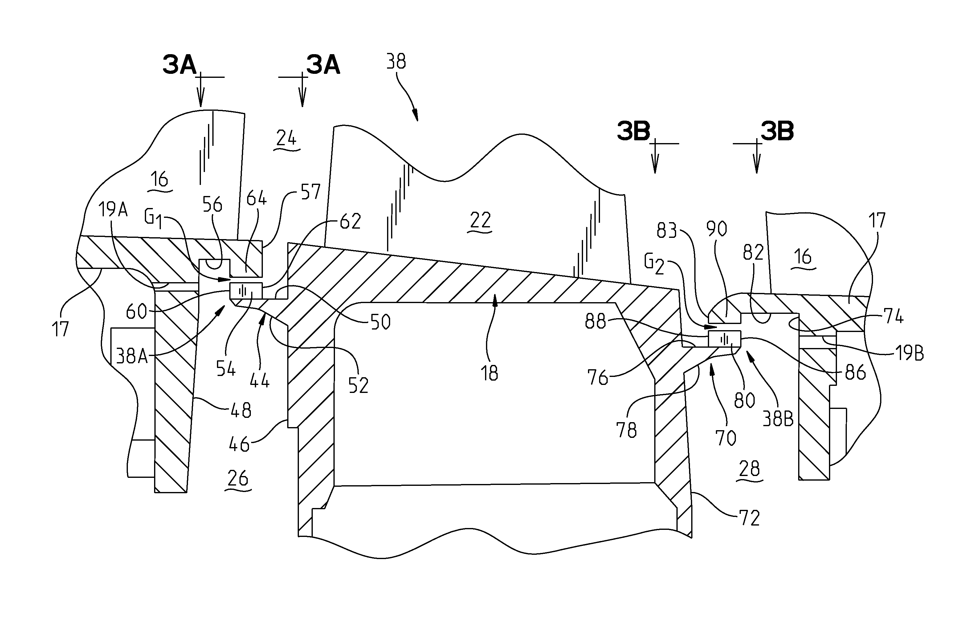
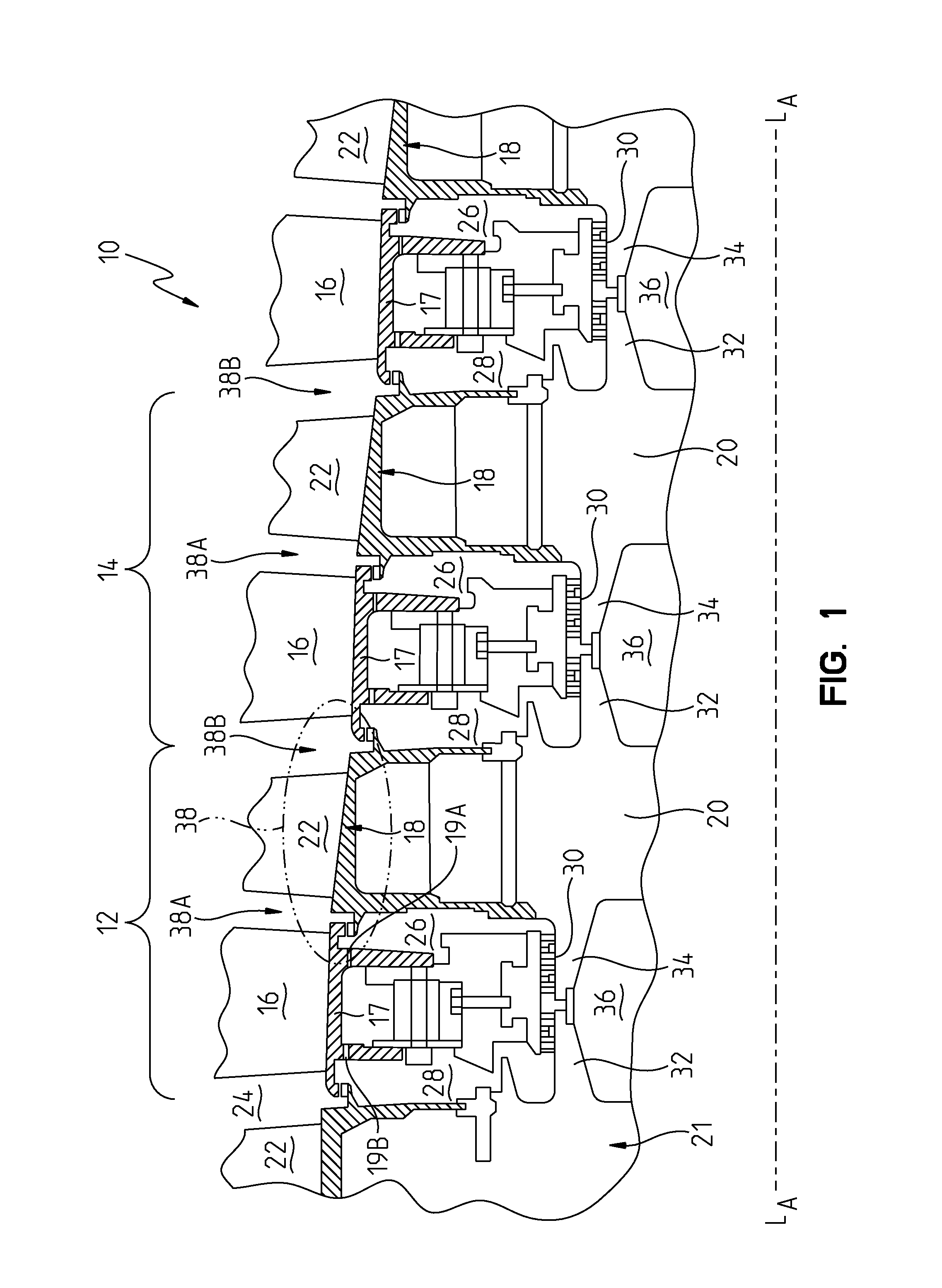
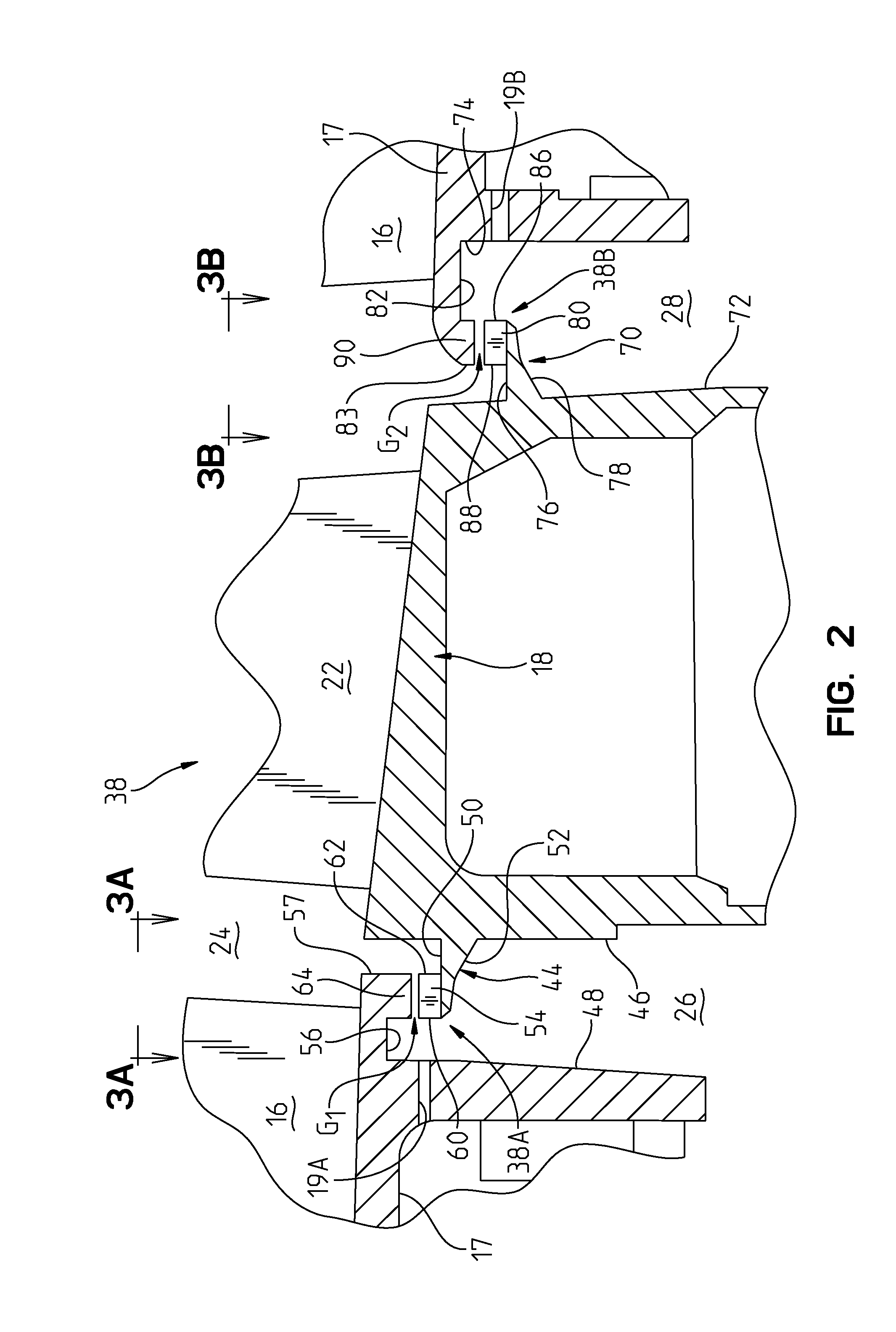
[0016]Referring to FIG. 1, a portion of a turbine engine 10 is illustrated diagrammatically including adjoining stages 12, 14, each stage comprising an array of stationary components, illustrated herein as vanes 16 suspended from an outer casing (not shown) and affixed to an annular inner shroud 17, and an array of rotating blade structures 18 supported on a disc structure 20 for rotation on a turbine rotor 21. The vanes 16 and the blade structures 18 are positioned circumferentially within the engine 10 with alternating rows of vanes 16...


PUM


Abstract

A seal assembly that limits gas leakage from a hot gas path to one or more disc cavities in a turbine engine. The seal assembly includes a seal apparatus that limits gas leakage from the hot gas path to a respective one of the disc cavities. The seal apparatus comprises a plurality of blade members rotatable with a blade structure. The blade members are associated with the blade structure and extend toward adjacent stationary components. Each blade member includes a leading edge and a trailing edge, the leading edge of each blade member being located circumferentially in front of the blade member's corresponding trailing edge in a direction of rotation of the turbine rotor. The blade members are arranged such that a space having a component in a circumferential direction is defined between adjacent circumferentially spaced blade members.

Description


Claims


Application Information

Patent Timeline
Owner SIEMENS ENERGY INC
Why Eureka
Try Eureka