
Centrifugal fan

a centrifugal fan and fan body technology, applied in the direction of machines/engines, liquid fuel engines, other chemical processes, etc., can solve the problems of noise generated in the blower, noise generally generated by the blower, noise occurring, etc., and achieve the effect of reducing the generated nois

Inactive Publication Date: 2010-03-25
SAMSUNG ELECTRONICS CO LTD
View PDF9 Cites 14 Cited by
  • Summary
  • Abstract
  • Description
  • Claims
  • Application Information

AI Technical Summary

Benefits of technology

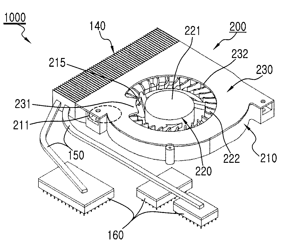
[0012]Accordingly, an object of the present invention is to provide a centrifugal fan for reducing noise generated when air sucked into a scroll housing of the centrifugal fan is discharged through a discharge port.
[0013]Another object of the present invention is to provide a centrifugal fan for reducing noise generated at the neighborhood of a cutoff portion by controlling air sucked around the cutoff portion when air sucked into a scroll housing of the centrifugal fan is discharged through a discharge port.
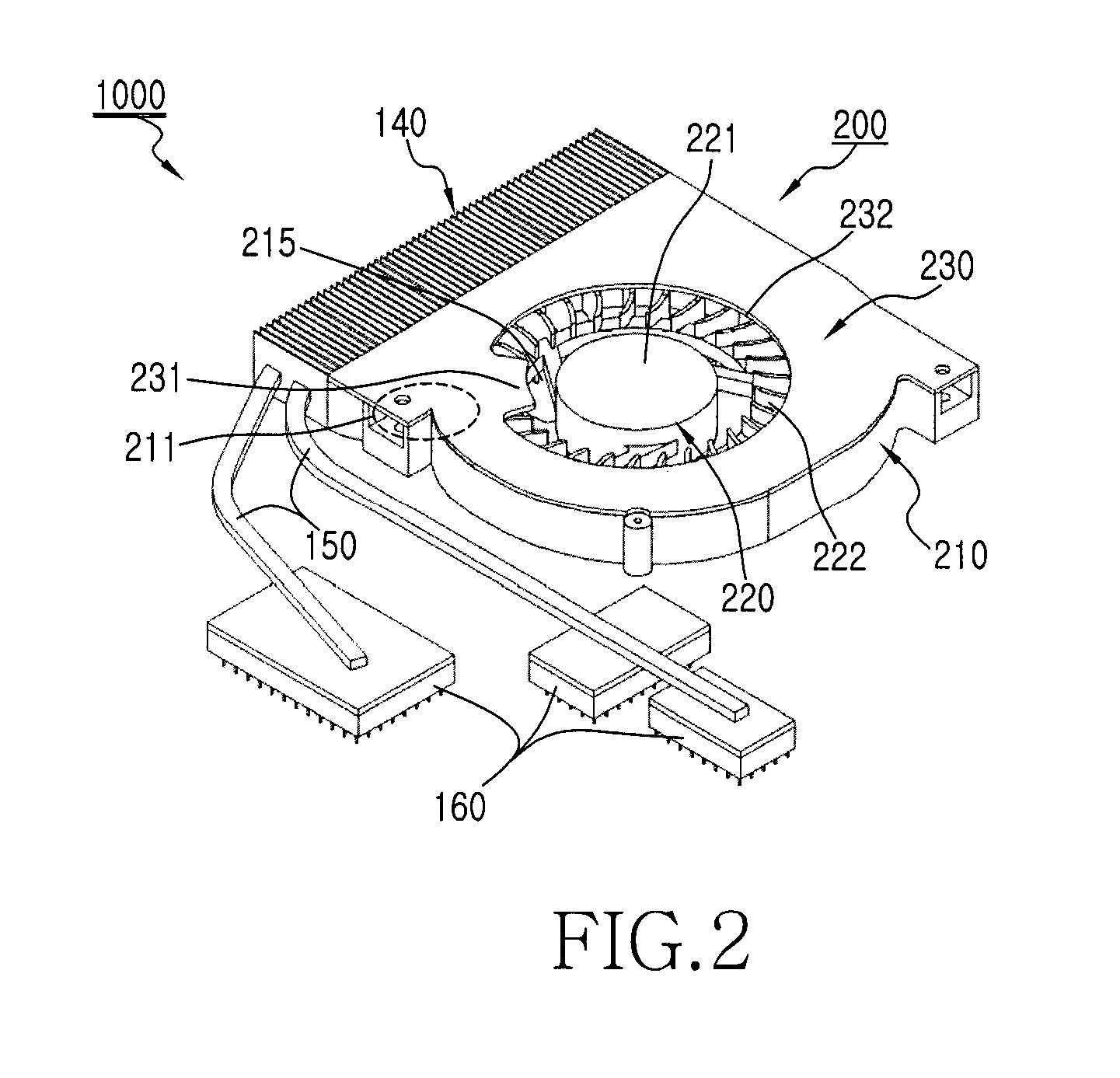
[0014]In accordance with an aspect of the present invention, a centrifugal fan is provided. The centrifugal includes a housing including a suction port and a discharge port, a spiral impeller coupled with a motor to suck air through the suction port of the housing in a rotation-axis direction and discharge the sucked air through the discharge port in a direction perpendicular to a rotation-axis, and a suction interrupting member preventing air from being sucked into a neighborhood of the cutoff portion through the suction port, wherein the housing further includes an outwardly curved cutoff portion at a side of the discharge port.
[0015]In accordance with another aspect of the present invention, a computer cooling fan is provided. The computer cooling fan includes a housing including a suction port and a discharge port, a spiral impeller couple with a motor to suck air through the suction port of the housing in a rotation-axis direction and discharge the sucked air through the discharge port in a direction perpendicular to a rotation-axis, and a suction interrupting member preventing air from being sucked into a neighborhood of the cutoff portion through the suction port, wherein the housing further includes an outwardly curved cutoff portion at a side of the discharge port.

Problems solved by technology

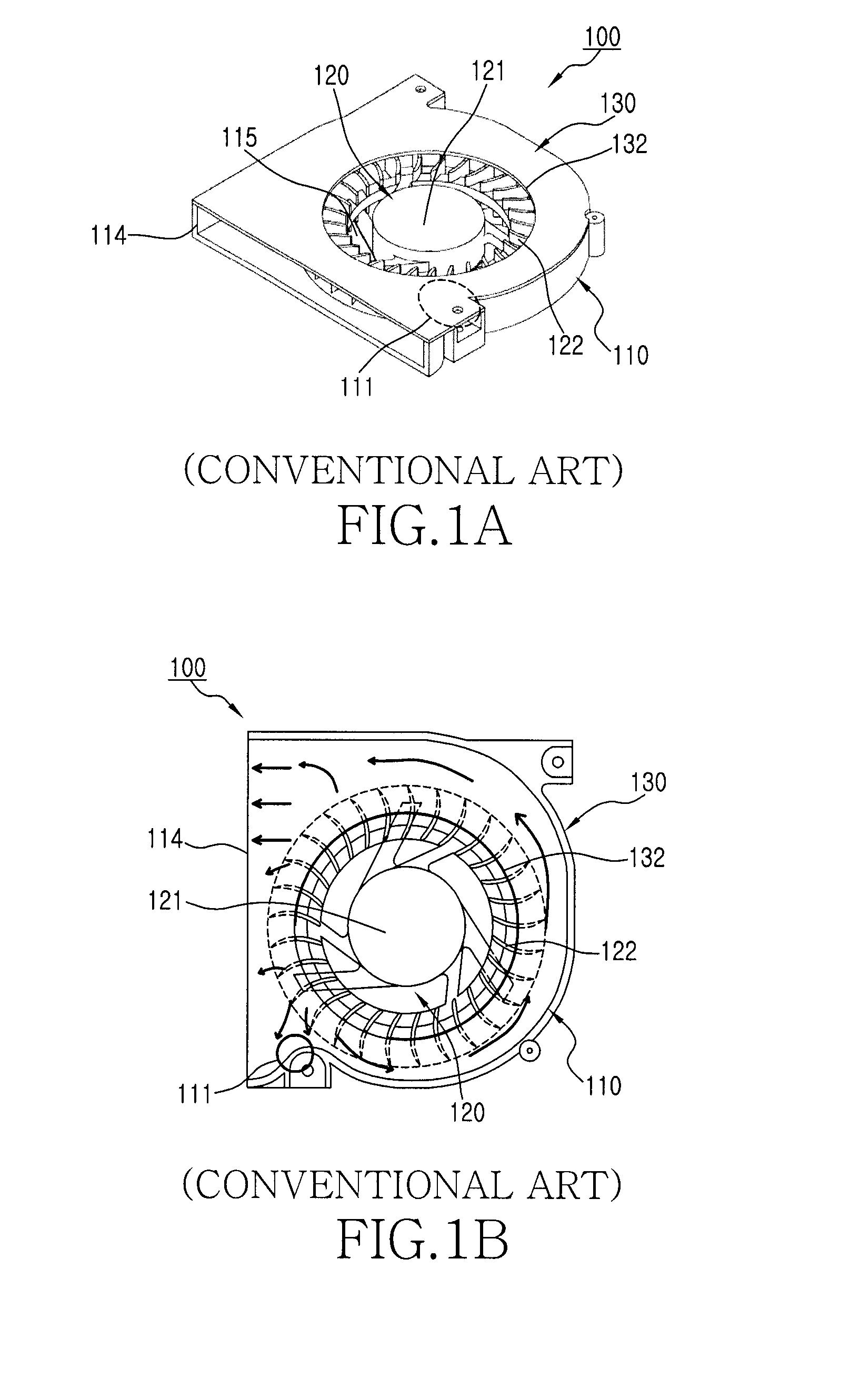
The blowers generally generate noise due to the non-uniform distribution of velocity and pressure when the sucked air is discharged.
The noise generated in the blowers may occur by vibration of a structure or the air flow itself.
When the external air is sucked into the fan and then discharged, noise occurs because of the non-uniform distribution of velocity and pressure of the air flow.

Method used


Image

  • Centrifugal fan
  • Centrifugal fan
  • Centrifugal fan

Examples


Embodiment Construction

[0025]The following description, with reference to the accompanying drawings, is provided to assist in a comprehensive understanding of exemplary embodiments of the invention as defined by the claims and their equivalents. It includes various specific details to assist in that understanding but these are to be regarded as merely exemplary. Accordingly, those of ordinary skill in the art will recognize that various changes and modifications of the embodiments described herein can be made without departing from the scope and spirit of the invention. Also, descriptions of well-known functions and constructions are omitted for clarity and conciseness.

[0026]The terms and words used in the following description and claims are not limited to the bibliographical meanings, but, are merely used by the inventor to enable a clear and consistent understanding of the invention. Accordingly, it should be apparent to those skilled in the art that the following description of exemplary embodiments o...


PUM


Abstract

A centrifugal fan includes a housing, a spiral impeller, a suction interrupting member. The housing includes a suction port and a discharge port. The housing further includes an outwardly curved cutoff portion at a side of the discharge port. The spiral impeller is coupled with a motor to suck air through the suction port of the housing in a rotation-axis direction and discharge the sucked air through the discharge port in a direction perpendicular to a rotation-axis. The suction interrupting member prevents air from being sucked into a neighborhood of the cutoff portion through the suction port.

Description

CLAIM OF PRIORITY[0001]This application claims the benefit of the earlier filing date, under 35 U.S.C. §119, to that patent application filed in the Korean Intellectual Property Office on Sep. 19, 2008 and assigned Serial No. 10-2008-0091954, the contents of which are incorporated herein by reference.BACKGROUND OF THE INVENTION[0002]1. Field of the Invention[0003]The present invention relates to the field of centrifugal fans and more particularly, to a centrifugal fan for reducing noise generated in the area of a cutoff when air sucked into a scroll housing is discharged through a discharge port.[0004]2. Description of the Related Art[0005]Blowers or fans are devices that generate an air flow. Such a blower includes an impeller for generating an air flow and a housing for guiding the air flow generated by the impeller. Blowers may be selected according to their application and operation. Industrial blowers may be mainly used for various intake / exhaust systems, such as air conditioni...

Claims


Application Information

Patent Timeline
IPC IPC(8): F04D29/44
CPCF04D29/422F04D29/582F04D29/4226F04D25/08F04D29/002F04D29/281F04D29/30F04D29/403F05D2210/12Y10S415/00Y10S416/00Y10S417/00
Inventor KOO, KYUNG-HA
Owner SAMSUNG ELECTRONICS CO LTD
Learn More