Braking process for an airplane

a technology for airplanes and braking systems, applied in aircraft braking arrangements, navigation instruments, instruments, etc., can solve problems such as damage to front landing gears, rapid derotation of airplanes, damage that can go as far as breakage, and achieve the effect of reducing braking possibilities

Inactive Publication Date: 2010-03-25
AIRBUS OPERATIONS (SAS)
View PDF3 Cites 7 Cited by
  • Summary
  • Abstract
  • Description
  • Claims
  • Application Information

AI Technical Summary

Benefits of technology

The described system for controlling an aircraft's brakes has two main features: it allows for automatic adjustment of the brakes based on certain measurements (such as air pressure or temperature) and it prevents excessive wear and tear on the brakes by reducing unnecessary modifications to the brabing commands. This means that even if there are repeated periods of high-speed braking during which the pilot may be unable to control them manually, the system will still maintain effective braking performance.

Problems solved by technology

The technical problem addressed in this patent is to prevent damage to the front landing gear of an aircraft during landing when the main landing gear touches the ground before the front landing gear, while also ensuring maximum braking capacity.

Method used


Image

  • Braking process for an airplane
  • Braking process for an airplane

Examples


Embodiment Construction

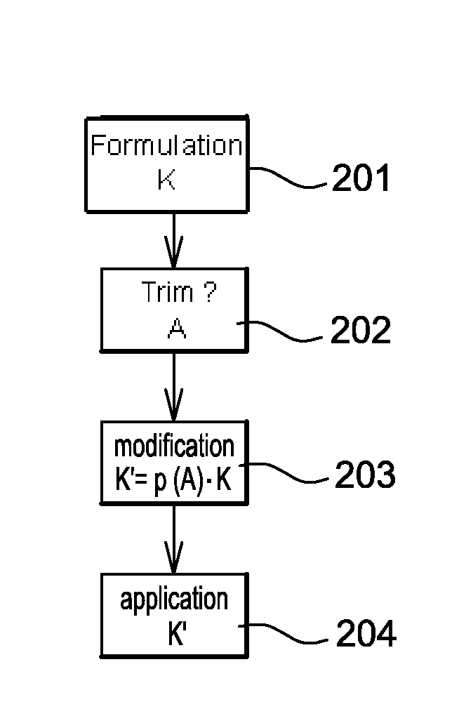
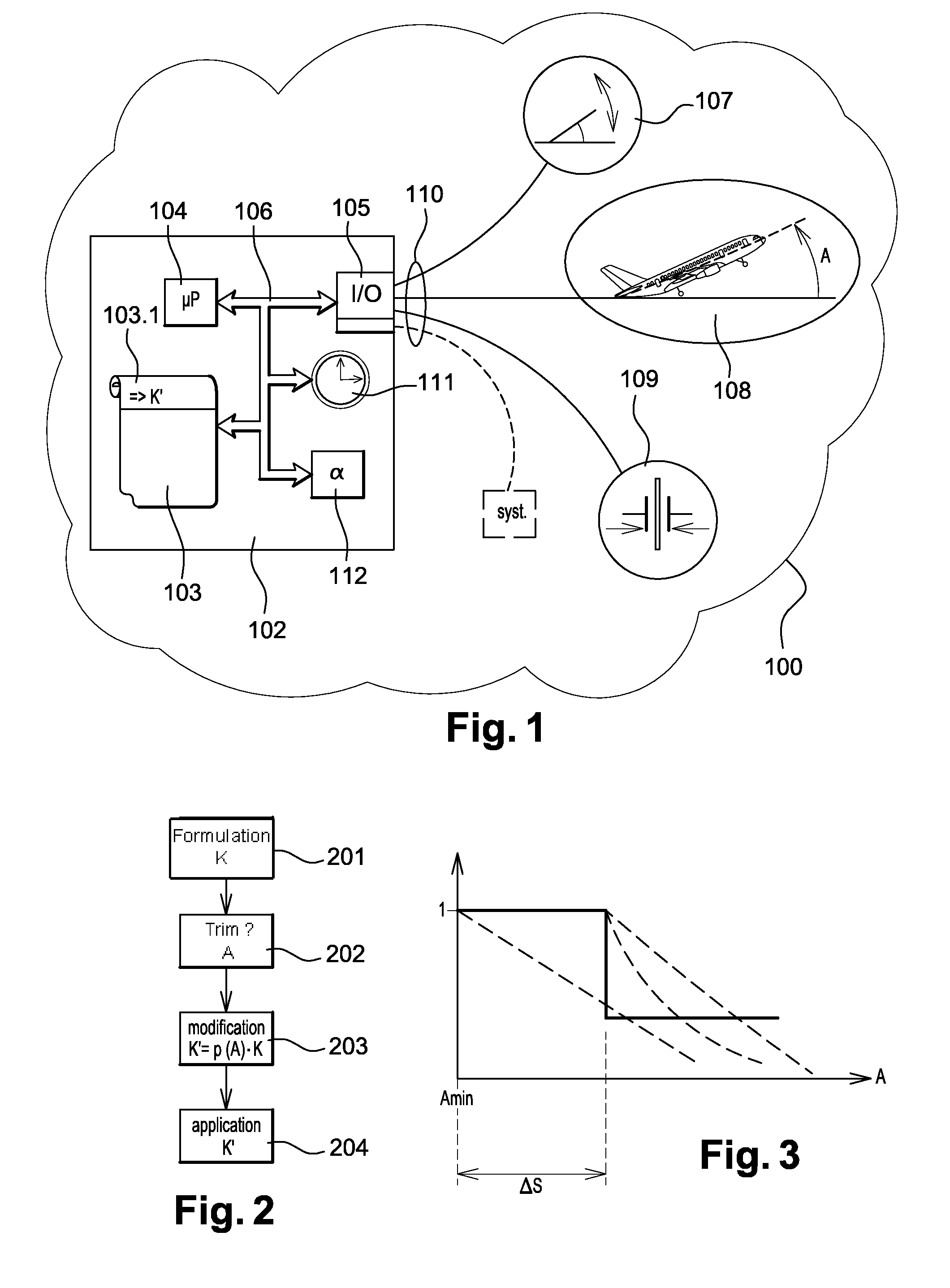
[0038]FIG. 1 is a schematic, functional view of certain elements of an aircraft 101. FIG. 1 shows, in particular, that the aircraft 101 has a logic 102 programmed according to instruction codes recorded in a memory 103. The programmed logic 102 is then designated as a processing device 102. The device 102 also has a microprocessor 104 and input / output circuits 105. Elements 103 to 105 are interconnected by a bus 106.

[0039]The device 102 is designated, in practice, by the term “calculator.”

[0040]The memory 103 has at least some instruction codes for implementing the process in the invention. These instruction codes are recorded in a zone 103.1 of the memory 103.

[0041]The circuits 105 allow the device 102 to be connected to the other communicating devices of the aircraft 101. For the invention, these communicating devices are at least:[0042]a command interface device 107 for braking. It is with this device 107 that the pilot of the aircraft 101 controls the braking of said aircraft.[0...


PUM


Abstract

An aircraft braking adaptation process is used to prevent rapid derotation of an aircraft causing damage to the front landing gear by formulating a braking command, applying the command to at least one brake, adapting the braking command by acquiring the aircraft trim and modifying the braking commands as a function of the aircraft trim.
This process limits the derotation speed and preserves the front landing gear.

Description


Claims


Application Information

Patent Timeline
Owner AIRBUS OPERATIONS (SAS)
Why Eureka
Try Eureka