Dust capture device and projection type image display apparatus

Active Publication Date: 2010-04-01
PANASONIC CORP
View PDF6 Cites 12 Cited by
  • Summary
  • Abstract
  • Description
  • Claims
  • Application Information

AI Technical Summary

Benefits of technology

[0017]According to the present invention, not only fine dust can be removed by the electrostatic filter but also the filter is always in a favorable condition by being automatically renewed and cleaned even over long hours of use. Thus, the dust removing capability can be maintained for lo

Problems solved by technology

Thus, they may be damaged thermally unless they are cooled appropriately.
Further, an electrostatic filter that can collect much smaller dust cannot be cleaned, so that it needs to be replaced with a new filter every several hundred hours.
Consequently, since they are not in an installed position where filter renewal can be carried out easily, the filters may not be always in an adequate condition.
The urethane filter prevents the entry of dust by capturing the dust physically with small openings but it cannot prevent the entry of dust smaller than 10 μm.
Therefo

Method used


Image

  • Dust capture device and projection type image display apparatus
  • Dust capture device and projection type image display apparatus
  • Dust capture device and projection type image display apparatus

Examples


Example

EMBODIMENT 1

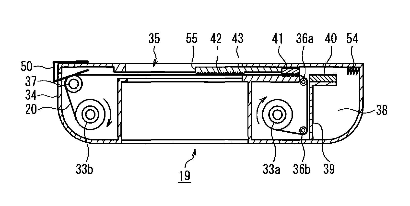
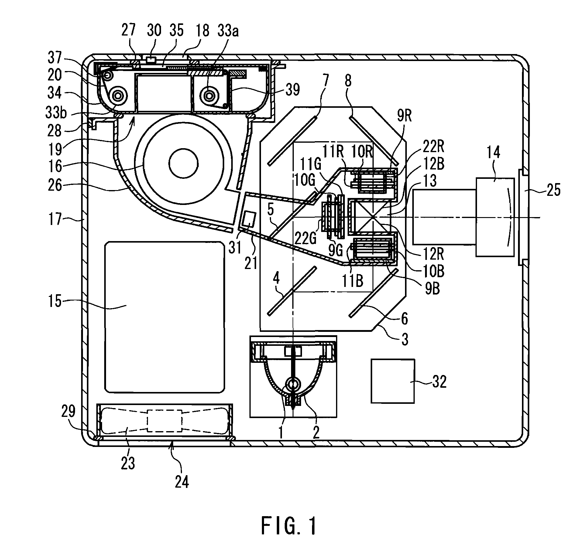
[0064]FIG. 1 is a cross-sectional view showing the overall planar configuration of a projection type image display apparatus according to Embodiment 1 of the present invention. The present embodiment is directed to improvements in a dust capture device used in a projection type image display apparatus, in particular to controlling the operation of the dust capture device. Therefore, since there are no specific limitations to the optical configuration, a typical optical configuration may be used in the present embodiment. Accordingly, in the following description, the optical configuration will be discussed only briefly.

[0065]In FIG. 1, light emitted by a lamp 1 as a light source is reflected by a reflection mirror 2 frontwards, and enters an optical unit 3. The incident light is separated into red, green and blue colored light beams through dichroic mirrors 4 and 5 and total reflection mirrors 6, 7 and 8.

[0066]Subsequently, the intensity of the respective colored light...

Example

EMBODIMENT 2

[0113]A projection type image display apparatus according to Embodiment 2 of the present invention employs a dust capture unit configured differently from that in Embodiment 1 but to which the method of controlling the dust capture unit in Embodiment 1 shown in FIG. 6 can be applied. FIG. 7 is a cross-sectional view showing the entire planar configuration of the projection type image display apparatus according to the present embodiment. Since this device has an optical configuration, etc., substantially similar to those in Embodiment 1, the same portions will be denoted with the same reference numerals and the description thereof will not be repeated.

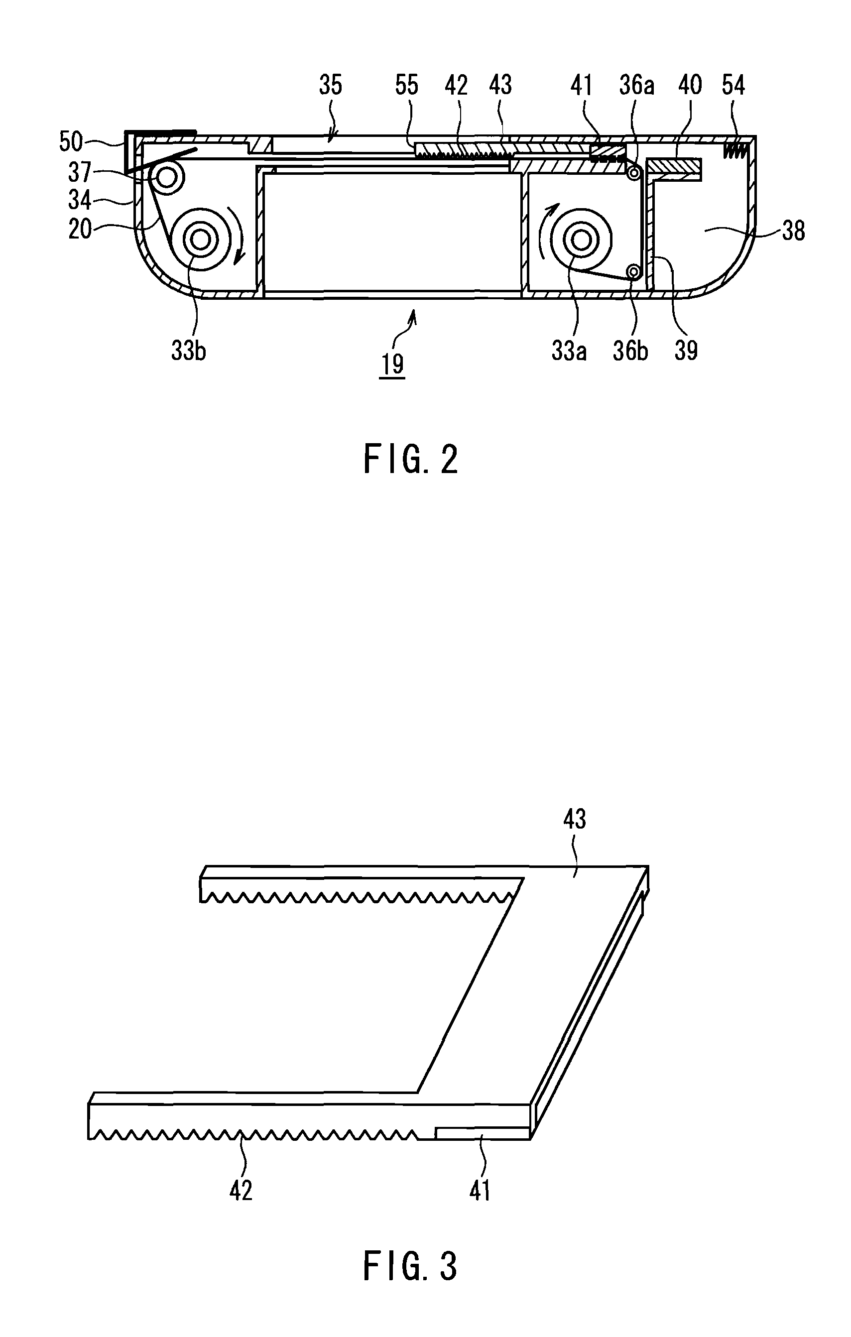
[0114]In the present embodiment, a dust capture unit 60 having a different configuration from the dust capture unit 19 in Embodiment 1 is used. In the dust capture unit 60, a filter cleaning unit is composed of a rotation brush 64 instead of the fixed brush 40 and the movable brush 41 used in the dust capture unit 19 in Em...

Example

EMBODIMENT 3

[0133]FIG. 12 is a flowchart showing a partial procedure of a renewing operation performed in a dust capture unit in Embodiment 3 of the present invention. The present embodiment is directed to the specific configuration of Step S2 (determining the condition for starting the renewing operation) in the procedure of the renewing operation shown in FIG. 6. Therefore, the procedural steps subsequent to Step S3 are not shown in the drawing. The procedure in the present embodiment is applicable when a projection type image display apparatus employs an entire configuration and a dust capture unit employs a configuration similar to those in Embodiment 1 or 2.

[0134]In the present embodiment, the condition for starting the renewing operation is set on the basis of the state of clogging of the filter detected by the air volume sensor 31. In this connection, since a detection output of the air volume sensor31 is affected by outside air temperature, it is desirable to compensate for ...


PUM

PropertyMeasurementUnit
Temperatureaaaaaaaaaa
Timeaaaaaaaaaa
Poweraaaaaaaaaa

Abstract

The present invention includes: a rolled filter stretched between first and second winding shafts and, unused part of the filter being wound around the second winding shaft; a brush provided between the first and the second winding shafts so as to come into contact with a surface of the filter; a feeding mechanism for driving the first and the second winding shafts to take up or rewind the filter; and a feeding control unit for controlling the feeding mechanism. When activating a renewing operation for feeding unused part of the filter from the second winding shaft, the feeding control unit controls the feeding mechanism such that once the filter is taken up by the first winding shaft by an take-up amount La, the filter is rewound by the second winding shaft by a rewind amount Lb, and La and Lb satisfy a relationship La≧Lb. Without increasing the amount of the filter or the size of the device itself, the present invention can deliver adequate performance even in a dusty environment by a small number of filter renewing operations.

Description

BACKGROUND OF INVENTION[0001]1. Field of the Invention[0002]The present invention relates to dust capture devices using a filter, in particular to a dust capture device having the capability of automatically renewing and cleaning a filter, and a projection type image display apparatus using the dust capture device.[0003]2. Description of Related Art[0004]Projection type image display apparatuses such as a projector include image display elements, such as a liquid crystal panel and a digital mirror device (DMD), and produce large-screen images by concentrating strong light from a light source, such as a lamp, onto the image display elements, and magnifying and projecting optical images formed by modulating the strong light in accordance with input image signals.[0005]The image display elements that are subjected to strong light, the light source itself, the device power supply and the like generate a large amount of heat. Thus, they may be damaged thermally unless they are cooled app...

Claims


Application Information

Patent Timeline
IPC IPC(8): B01D46/46B01D46/18B01D46/28B01D46/44B01D46/16
CPCB03C3/017B03C3/28B03C3/64H04N9/3197H04N9/3105H04N9/3141G03B21/16
Inventor YAMAGISHI, SHIGEKAZUOIDATE, SHINGOTANAKA, MASATOKOTAKA, MITSURU
Owner PANASONIC CORP
Why Eureka
Try Eureka