Gas sensor

Active Publication Date: 2012-11-15
HONDA MOTOR CO LTD
View PDF1 Cites 0 Cited by
  • Summary
  • Abstract
  • Description
  • Claims
  • Application Information

AI Technical Summary

Benefits of technology

[0009]Accordingly, an object of the present invention is to provide a gas sensor which needs no temperature sensor for detecting a temperature of a heater for preventing dew condensation.

Problems solved by technology

However, as mentioned hereinbefore, if the temperature sensor for detecting the heater temperature is included, the number of the components of the hydrogen sensor increases, resulting in the difficulty and inconvenience for downsizing the hydrogen sensor.

Method used


Image

  • Gas sensor
  • Gas sensor
  • Gas sensor

Examples


first embodiment

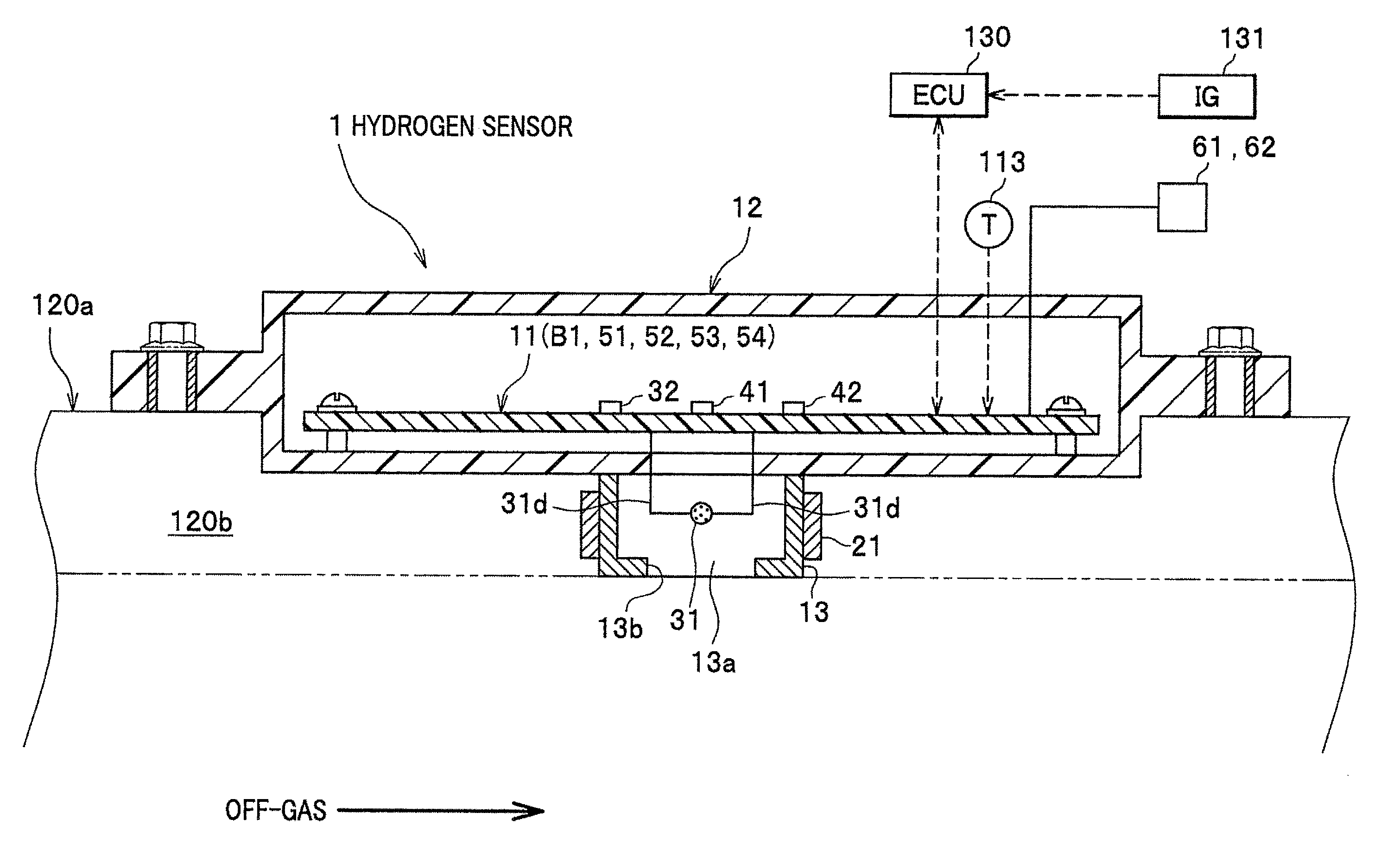
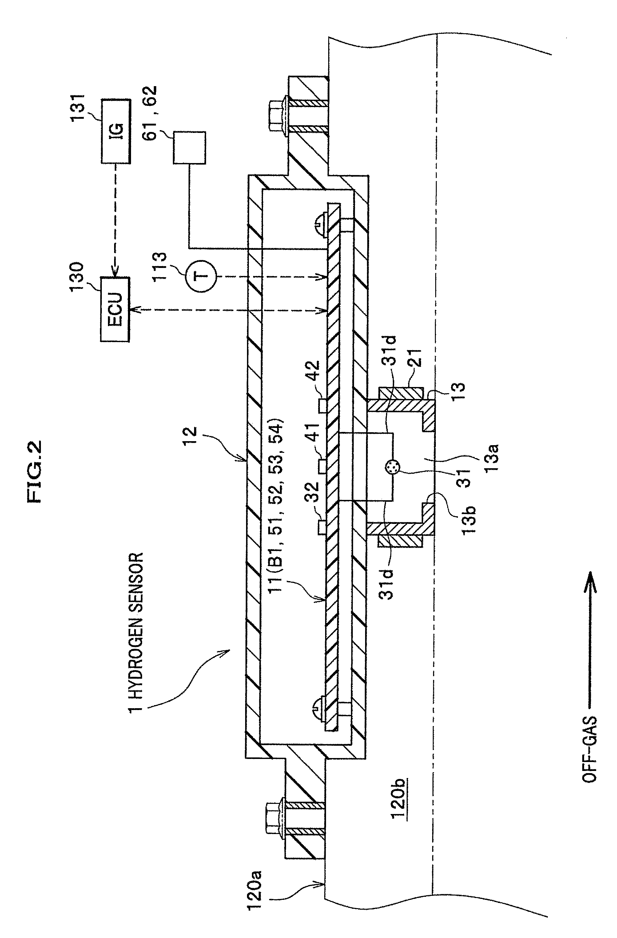
[0044]Hereinafter, will be explained the first embodiment of the present invention referring to FIGS. 1 to 9.

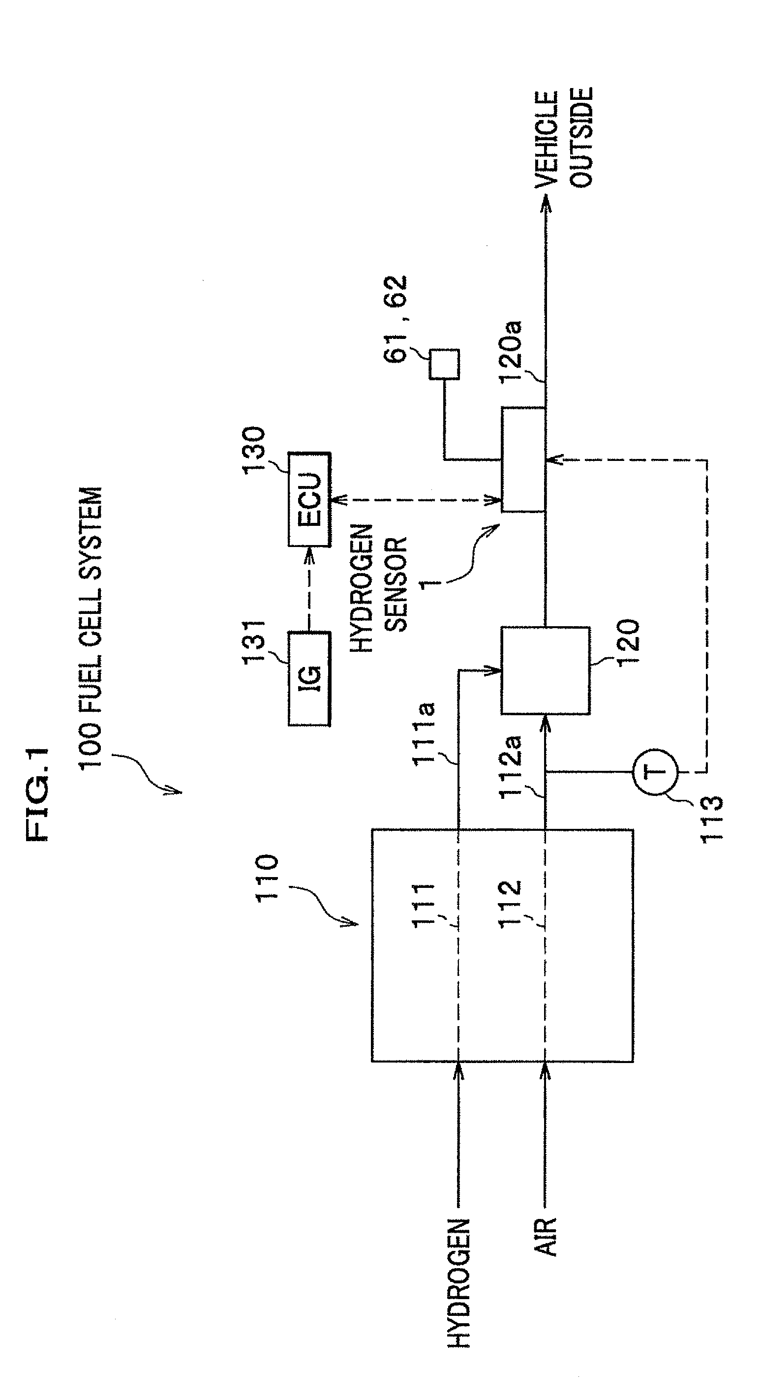
[0045]First, a fuel cell system 100 incorporating a hydrogen sensor 1 (or gas sensor) will be explained. The fuel cell system 100 is mounted on a fuel cell vehicle (or moving body), comprising a fuel cell stack 110 (or fuel cell), a diluter 120, a temperature sensor 113, a hydrogen sensor 1, and ECU 130 (or Electric Control Unit).

[0046]

[0047]The fuel cell stack 110 is a polymer electrolyte fuel cell (or PEFC) and constructed by stacking a plurality of unit cells; the unit cell being made by sandwiching a membrane electrode assembly (or MEA) between separators (not shown). The MEA comprises an electrolytic membrane (or polymer electrolyte membrane), an anode and a cathode; the anode and the cathode sandwiching the MEA therebetween. An anode flow passage 111 and a cathode flow passage 112, comprised of grooves or through holes, are formed in each separator.

[0048]Further, when h...

modified example

[0131]Hereinbefore, an embodiment of the present invention has been explained. However, the present invention is not limited to the embodiment. Therefore, the embodiment may be appropriately combined with a construction in another embodiment described hereinafter, or may be modified as mentioned below.

[0132]In the aforementioned embodiment, the construction in which gas to be detected is hydrogen has been exemplified. However, other gases may be detected.

[0133]Further, in the aforementioned embodiment, the construction in which a hydrogen sensor 1 is a catalytic combustion type has been exemplified. However, other types, for example, a gas sensor in a semiconductor type may be utilized.

[0134]Moreover, in the aforementioned embodiment, the construction in which a fuel cell vehicle is equipped with a fuel cell system 100 has been exemplified. However, other moving bodies, for example, a motorcycle, a train, a ship may be equipped with a fuel cell system 100. Furthermore, the present i...

second embodiment

[0135]Next, will be explained the second embodiment referring to FIGS. 10 to 13. Note the different parts form the first embodiment will be only explained, by omitting the same parts.

[0136]>

[0137]As shown in FIG. 10, instead of the heater operation circuit 52 (see FIG. 4), a heater operation circuit 70 is included. Further, the microcomputer 51 does not control the heater operation circuit 70. Hereby, the control processing thereof is omitted.

[0138]

[0139]As shown in FIG. 11, a heater operation circuit 70 comprises a bridge circuit B2, an amplifier 91, and a transistor (IGBT or the like).

[0140]The bridge circuit B2 comprises a first branched part 81 and a second branched part 82, and is constructed by connecting the first branched part 81 and the second branched part 82 with the outside power source in parallel. The first branched part 81 is constructed by connecting the heater 21 and the A resistor 83 in series. The second branched part 82 is constructed by connecting the B resistor...


PUM


Abstract

Provided is a gas sensor that needs no temperature sensor for detecting a temperature of a heater for preventing dew condensation. The gas sensor comprises a hydrogen sensor 1 including: an element housing 13 having a detection chamber 13a to which hydrogen is introduced; a detection element 31 arranged in the detection chamber 13a and detecting hydrogen; a heater 21 for heating the detection chamber 13a by heat generation via passing an electric current through the heater 21, a resistance value of the heater 21 being changed corresponding to a temperature of the detection chamber 13a; and a microcomputer 51 and a heater operation circuit 52 for controlling the heater 21. Herein, the microcomputer 51 controls a temperature of the detection chamber 13a by adjusting the electric current passing through the heater 21 based on the resistance value of the heater 21.

Description

CROSS REFERENCE TO RELATED APPLICATIONS[0001]This application claims the foreign priority benefit under Title 35, United State Code, 119 (a)-(d) of Japanese Patent Application No. 2011-106666, filed on May 11, 2011 in the Japan Patent Office, the disclosure of which is herein incorporated by reference in its entirety.BACKGROUND OF THE INVENTION[0002]1. Field of the Invention[0003]The present invention relates to a gas sensor.[0004]2. Description of Related Art[0005]Recently, a fuel cell which is expected for a power source for a fuel cell vehicle or the like discharges hydrogen (or gas to be detected) not consumed by power generation from an anode of the fuel cell. The hydrogen is diluted with cathode off-gas (or dilution gas) flowing from a cathode of the fuel cell, and subsequently discharged to the outside of the vehicle (or outside). Then, the concentration of hydrogen in the gas discharged to the outside of the vehicle (or diluted gas) is detected by a hydrogen sensor (or gas s...

Claims


Application Information

Patent Timeline
IPC IPC(8): B01J19/12
CPCG01N27/16Y02E60/50H01M8/04089G01N33/005
Inventor TSUKABAYASHI, SHUNJIOISHI, HIDETOSHIOKAJIMA, KAZUHIRO
Owner HONDA MOTOR CO LTD
Why Eureka
Try Eureka