Method and arrangement for detecting a leak in anesthesia system

a leak detection and anesthesia technology, applied in audible signalling systems, instruments, respirators, etc., can solve the problems of loose endotrahceal tube sealing, complicated assembly procedure, and high cost of expired gas

Active Publication Date: 2010-04-01
GENERAL ELECTRIC CO
View PDF49 Cites 73 Cited by
  • Summary
  • Abstract
  • Description
  • Claims
  • Application Information

AI Technical Summary

Benefits of technology

[0017]In another embodiment, an arrangement for detecting a leak in an anesthesia system includes a ventilator configured to control respiratory movements, including at least one flow sensor for measuring a ventilator gas flow added for an inspiration and removed for an expiration and a gas mixer for supplying a fresh gas flow for a respiration, including at least one flow sensor for measuring the fresh gas flow added. An arrangement for detecting a leak in an anesthesia system also includes a breathing circuit for conducting an expiration gas flow to the ventilator and for conducting the fresh gas flow from the gas mixer for the respiration and for conducting the ventilator gas flow added for the inspiration. An arrangement for detecting a leak in an anesthesia system further includes a leak analyzer for receiving information indicative of the measured gas flows of the flow sensors and which leak analyzer is configured to determine based on the information both the gas volume added and the gas volume removed and to compare these gas volumes to each other and to determine the anesthesia system leakage.
[0018]In yet another embodiment an arrangement for detecting a leak in an anesthesia system includes a ventilator configured to...

Problems solved by technology

An expired gas comprises a lot of expensive and environment-hostile anesthesia gases.
This assembly procedure may be complicated and is liable for errors causing leakages.
Therefore, all anesthesia machines enclose a breathing circuit leak test that is performed before the patient is connected and the operation begins.
Also an endotrahceal tube sealing may loose, or inadvertent loosening of some tubing may occur in the busy and often tight ...

Method used


Image

  • Method and arrangement for detecting a leak in anesthesia system
  • Method and arrangement for detecting a leak in anesthesia system
  • Method and arrangement for detecting a leak in anesthesia system

Examples


Embodiment Construction

[0023]Specific embodiments are explained in the following detailed description making a reference to accompanying drawings. These detailed embodiments can naturally be modified and should not limit the scope of the invention as set fort in the claims.

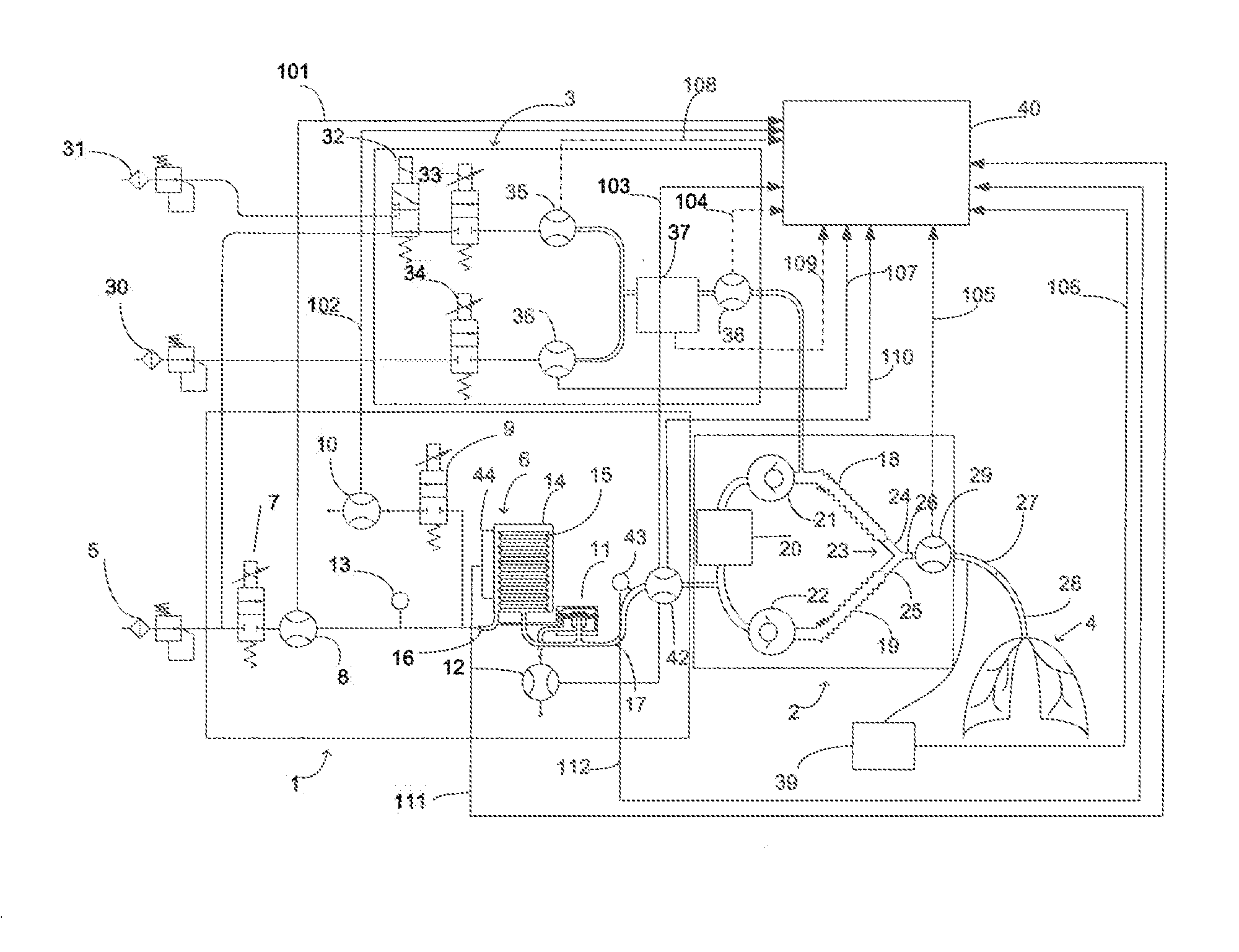
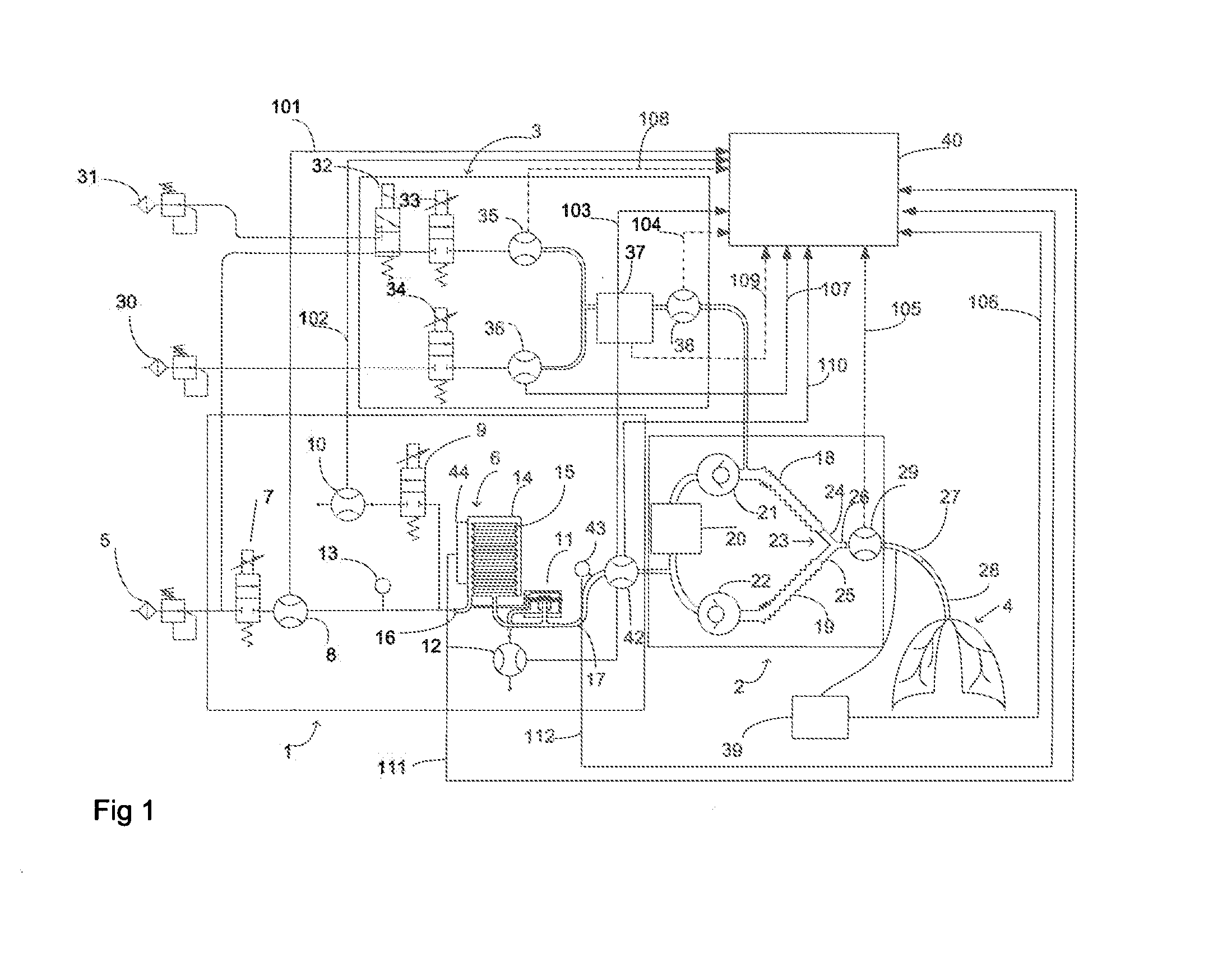
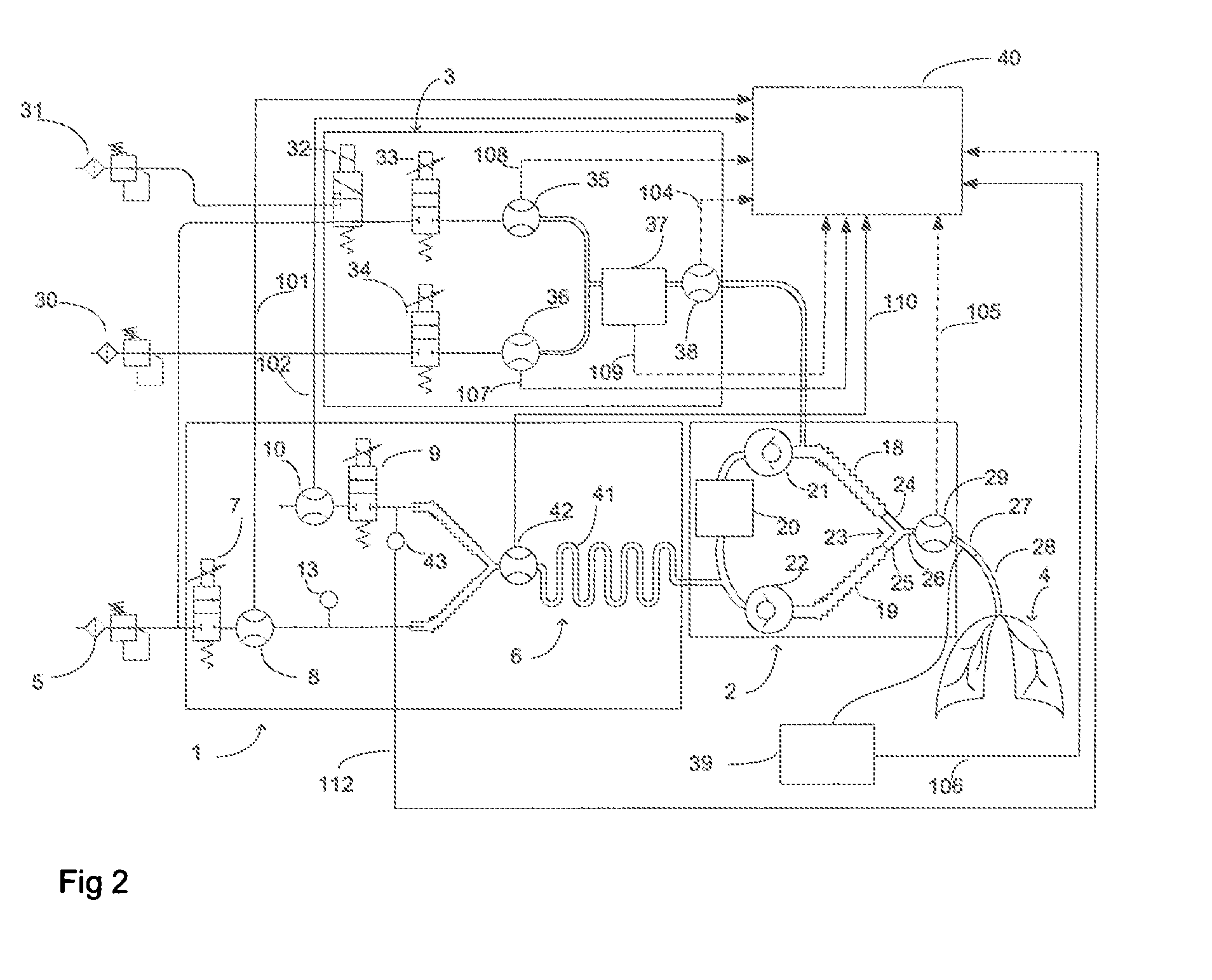
[0024]FIGS. 1 and 2 shows an arrangement for detecting a leak in an anesthesia system. Also a method for detecting a leak in an anesthesia system is disclosed. The anesthesia system comprises a ventilator 1, a breathing circuit 2, a fresh gas mixer 3 and a leak analyzer 40. A subject 4 is connected to the breathing circuit 2 by means of an endotracheal tube 28. According to an embodiment, measuring differences in a gas volume delivered into the breathing circuit 2 during an inspiration and removed from the breathing circuit 2 identifies a leak. Such leak detection requires sensors for a fresh gas flow, a ventilator gas flow for the inspiration, a ventilator gas flow for the expiration, and a scavenged gas flow. The gas volume removed du...


PUM


Abstract

A method and arrangement for detecting a leak in an anesthesia system. The method includes controlling respiratory movements by means of ventilator gas flows and measuring the ventilator gas flow added for an inspiration and removed for an expiration. The method also includes supplying a fresh gas flow for a respiration and measuring the fresh gas flow added for the respiration. The method further includes receiving information indicative of the measured gas flows, determining based on said received information both the gas volume added and the gas volume removed and comparing these determined gas volumes to each other. The method also includes determining based on comparing the anesthesia system leakage.

Description

CROSS-REFERENCE TO RELATED APPLICATIONS[0001]This application claims priority under 35 U.S.C. §119(a)-(d) or (f) to prior-filed, co-pending European patent application serial number 08396014.6, filed on Sep. 26, 2008, which is hereby incorporated by reference in its entirety.STATEMENT REGARDING FEDERALLY SPONSORED RESEARCH OR DEVELOPMENT[0002]Not ApplicableNAMES OF PARTIES TO A JOINT RESEARCH AGREEMENT[0003]Not ApplicableREFERENCE TO A SEQUENCE LISTING, A TABLE, OR COMPUTER PROGRAM LISTING APPENDIX SUBMITTED ON COMPACT DISC[0004]Not ApplicableBACKGROUND OF THE INVENTION[0005]1. Field of the Invention[0006]This disclosure relates generally to a method and an arrangement for detecting a leak in an anesthesia system.[0007]2. Description of Related Art[0008]Inhalation anesthesia is delivered using a re-breathing circuit comprising an inspiratory limb through which a patient gets an inspired breathing gas from a ventilator, an expiratory limb carrying an exhaled gas back to the ventilato...

Claims


Application Information

Patent Timeline
IPC IPC(8): A61M16/01
CPCA61M16/01A61M16/205A61M16/14A61M16/22A61M2016/0021A61M2016/0036A61M2202/0208A61M2202/0275A61M2205/15A61M2230/432A61M16/0081A61M16/085A61M16/125A61M16/204A61M16/104A61M2202/0283A61M16/209
Inventor HEINONEN, ERKKI PAAVOHAGGBLOM, TOM JAKOB
Owner GENERAL ELECTRIC CO
Why Eureka
Try Eureka