System and method for controlling a wind turbine during loss of grid power and changing wind conditions

a wind turbine and grid power technology, applied in the field of wind turbines, can solve the problems of limiting the speed of wind turbine yawing, unsatisfactory cable twisting, and the inability to yaw the wind turbine very slowly (about 0.5 degrees/s), and achieve the effect of substantially constant orientation of the nacelle of the wind turbin

Active Publication Date: 2010-04-01
GENERAL ELECTRIC CO
View PDF12 Cites 31 Cited by
  • Summary
  • Abstract
  • Description
  • Claims
  • Application Information

AI Technical Summary

Benefits of technology

The patent describes a wind turbine that has a control system to adjust the angle of its blades when there is no power grid to use. This helps to keep the turbine running in a safe and efficient way.

Problems solved by technology

The technical problem addressed in this patent is how to efficiently control wind turbines during grid loss and changes in wind conditions, especially under storm winds, to maintain a constant rotor speed and keep the uninterruptable power supply (UPS) active. The patent also aims to alleviate the need for a separate backup generator and to address the issue of cable twisting caused by yawing the wind turbine to keep the rotor perpendicular to the wind direction.

Method used


Image

  • System and method for controlling a wind turbine during loss of grid power and changing wind conditions
  • System and method for controlling a wind turbine during loss of grid power and changing wind conditions
  • System and method for controlling a wind turbine during loss of grid power and changing wind conditions

Examples


Embodiment Construction

[0020]Referring to the drawings wherein identical reference numerals denote the same elements throughout the various views,

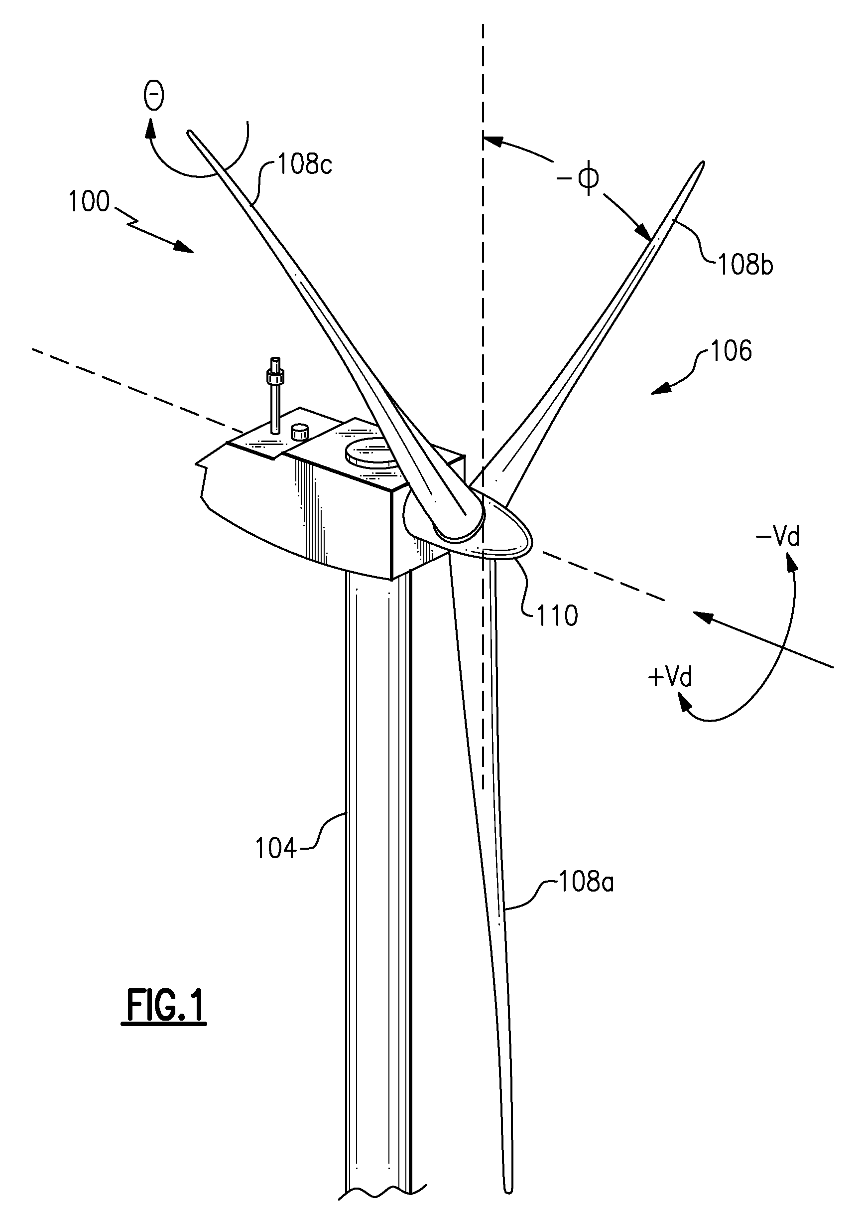
[0021]Referring now to FIG. 1, a wind turbine 100 in some configurations comprises a nacelle 102 mounted atop a tall tower 104, only a portion of which is shown in FIG. 1. The wind turbine 100 also comprises a rotor 106 that includes a plurality of rotor blades 108a, 108b and 108c attached to a rotating hub 110. Although the wind turbine 100 illustrated in FIG. 1 includes three rotor blades, there are no specific limits on the number of rotor blades 108 required by the invention.

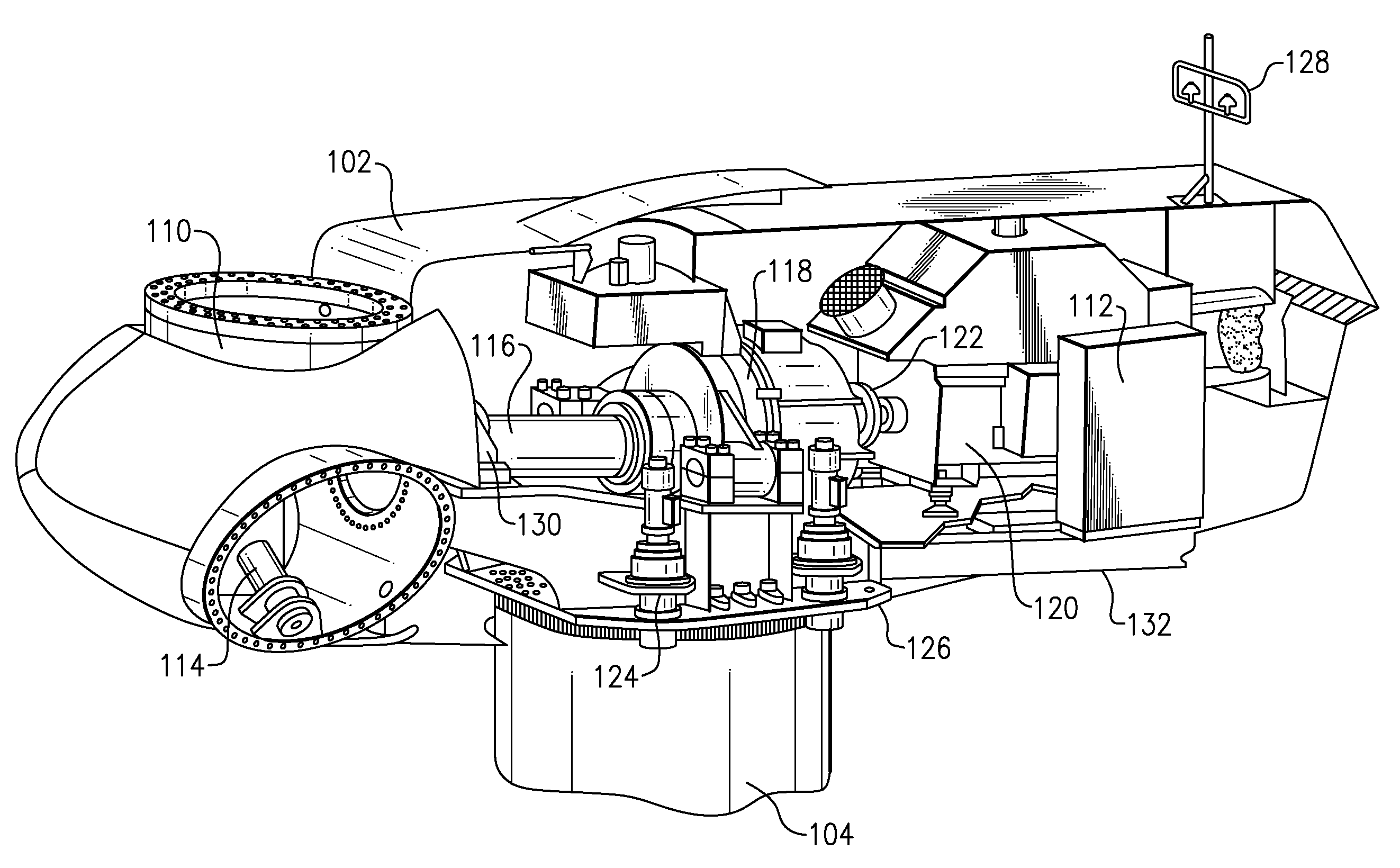
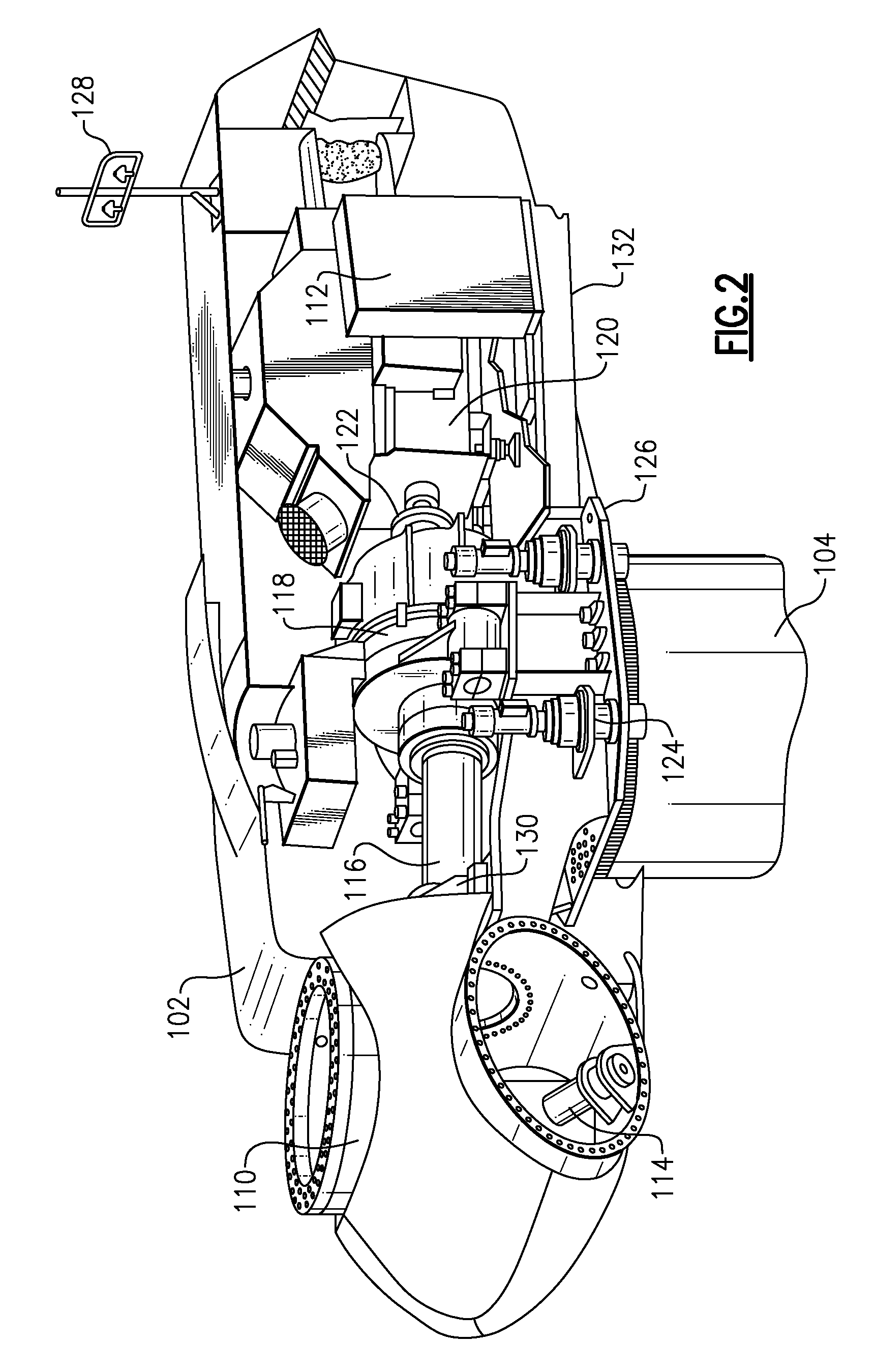
[0022]Referring now to FIG. 2, various components are housed in the nacelle 102 atop the tower 104 of the wind turbine 100. The height of the tower 104 is selected based upon factors and conditions known in the art. In some configurations, one or more microcontrollers within the control panel 112 comprise a control system are used for overall system monitoring and control including pitch...


PUM


Abstract

An apparatus and method for controlling a wind turbine having a plurality of blades such that the blade angle of each blade is continuously adjusted during loss of grid power relative to a wind direction relative to an orientation of the nacelle (i.e., yaw offset) and a rotor azimuth while keeping the orientation of the nacelle of the wind turbine substantially constant. The wind turbine is capable of pitching the blades a full 360 degrees and generating power from the rotation of the rotor shaft during loss of grid power.

Description


Claims


Application Information

Patent Timeline
Owner GENERAL ELECTRIC CO
Why Eureka
Try Eureka