
Liquid ejection head drive circuit, liquid ejection apparatus, and method of protecting liquid ejection head drive circuit

a drive circuit and liquid ejection head technology, applied in piezoelectric/electrostrictive/magnetostrictive devices, piezoelectric/electrostriction/magnetostriction machines, printing, etc., can solve the problems of short circuit, inability to protect the drive circuit, and the interface of the drive circuit, so as to avoid damage

Inactive Publication Date: 2010-04-01
FUJIFILM CORP
View PDF5 Cites 17 Cited by
  • Summary
  • Abstract
  • Description
  • Claims
  • Application Information

AI Technical Summary

Benefits of technology

[0025]The present invention has been contrived in view of the above-described circumstances, an object thereof being to provide a liquid ejection head drive circuit and a method of protecting such liquid ejection head drive circuit capable of avoiding the malfunction of the drive circuit and the like caused by the deterioration in the insulation resistance value and continuing the determination of abnormal insulation upon determining the abnormal insulation of piezoelectric elements arranged in the liquid ejection head.
[0026]In order to attain the aforementioned object, the present invention is directed to a liquid ejection head drive circuit, comprising: a drive voltage application device which applies drive voltage between a drive electrode and a common electrode of a piezoelectric element arranged in a liquid ejection head; a detection device which detects a current flowing in a common line which is electrically connected to the common electrode; an abnormal insulation determination device which determines a status of abnormal insulation of the piezoelectric element according to a detection result of the detection device; and a current limitation device which limits the current flowing in the common line within a prescribed range where the abnormal insulation determination device is enabled to determine the status of abnormal insulation, when the current flowing in the common line exceeds a reference value which is determined so that at least one of the detection device and the drive voltage application device is prevented from being overloaded.
[0027]According to the present invention, in the drive circuit for supplying the prescribed drive voltage to the liquid ejection head including the piezoelectric element, since the common current is limited when such common current exceeds the prescribed value upon determining the status of abnormal insulation of the piezoelectric elements according to the common current flowing in the common line that is electrically connected to the common electrode of the piezoelectric element, it is possible to avoid damages to the detection device or the elements configuring the drive circuit due to an overload. Moreover, since the common current is limited within a range where the status of abnormal insulation of the piezoelectric element can be determined, the status of abnormal insulation of the piezoelectric element can be determined even in a state where the common current is limited.

Problems solved by technology

Nevertheless, there are cases where the resistance value between the electrodes drops to several hundred kiloohms (kΩ) or less due to some kind of abnormality.
(1) the short circuit of electrodes due to a manufacturing defect;
(2) even though the electrodes were initially normal, the metal material that is used in the electrode migrates into the piezoelectric body due to a long-term operation, which eventually results in a short circuit; and
(3) the ink exudes to the live parts as a result of the insulation structure between the ink and the live parts being damaged, and current flowing between the electrodes through the ink.
Consequently, the enlargement of the drive circuit, the interface, and the inkjet head is inevitable.
Nevertheless, since the voltage to be applied to the piezoelectric elements 202 decreases for the amount of the foregoing voltage increase, there is a problem in that the ejection efficiency of the inkjet head deteriorates.
Hence, since this impairs the primary ink ejection function of the inkjet head, the increase in the resistance value of the monitor resistor 254 is not necessarily favorable.

Method used


Image

  • Liquid ejection head drive circuit, liquid ejection apparatus, and method of protecting liquid ejection head drive circuit
  • Liquid ejection head drive circuit, liquid ejection apparatus, and method of protecting liquid ejection head drive circuit
  • Liquid ejection head drive circuit, liquid ejection apparatus, and method of protecting liquid ejection head drive circuit

Examples


Embodiment Construction

General Composition of Inkjet Recording Apparatus

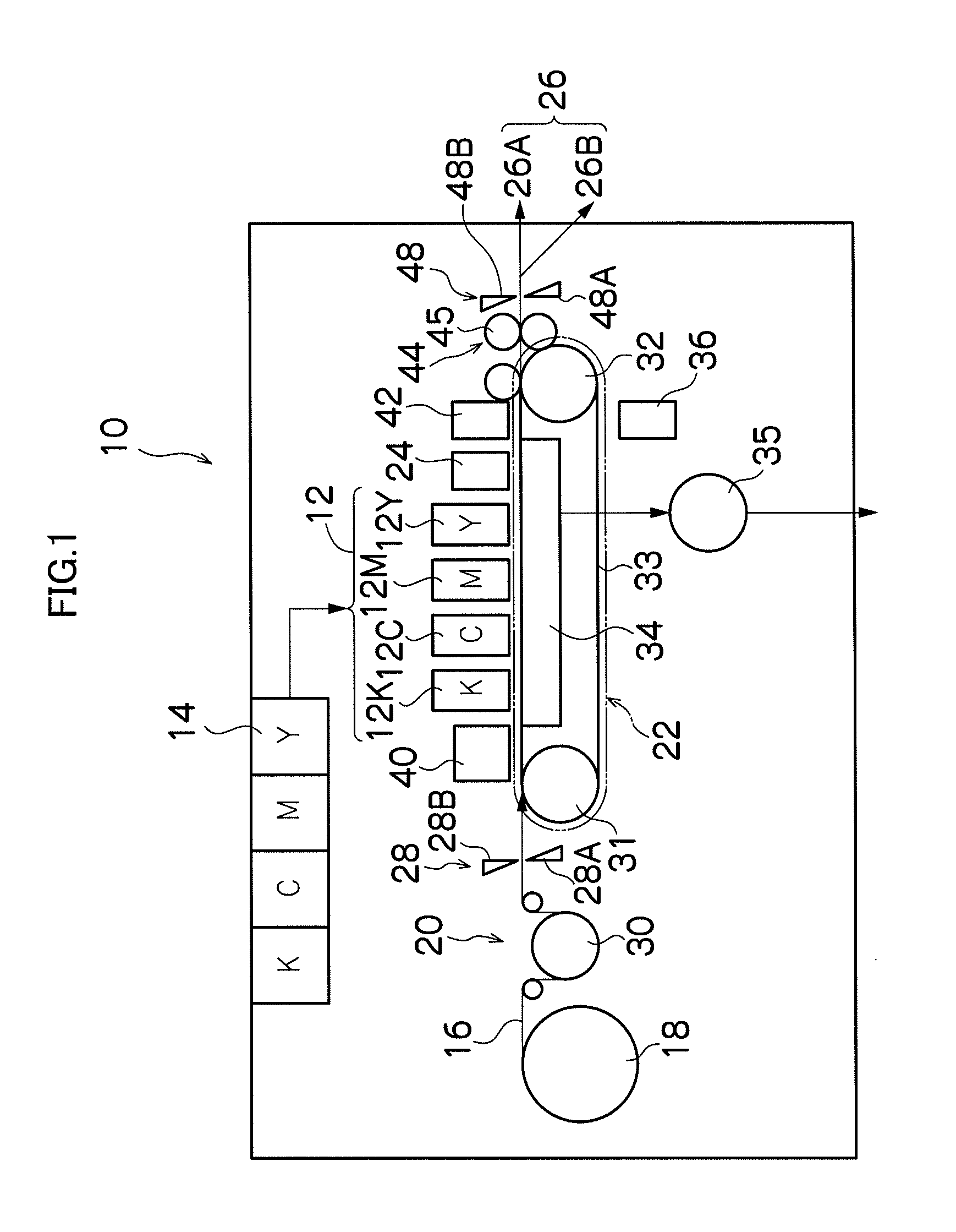
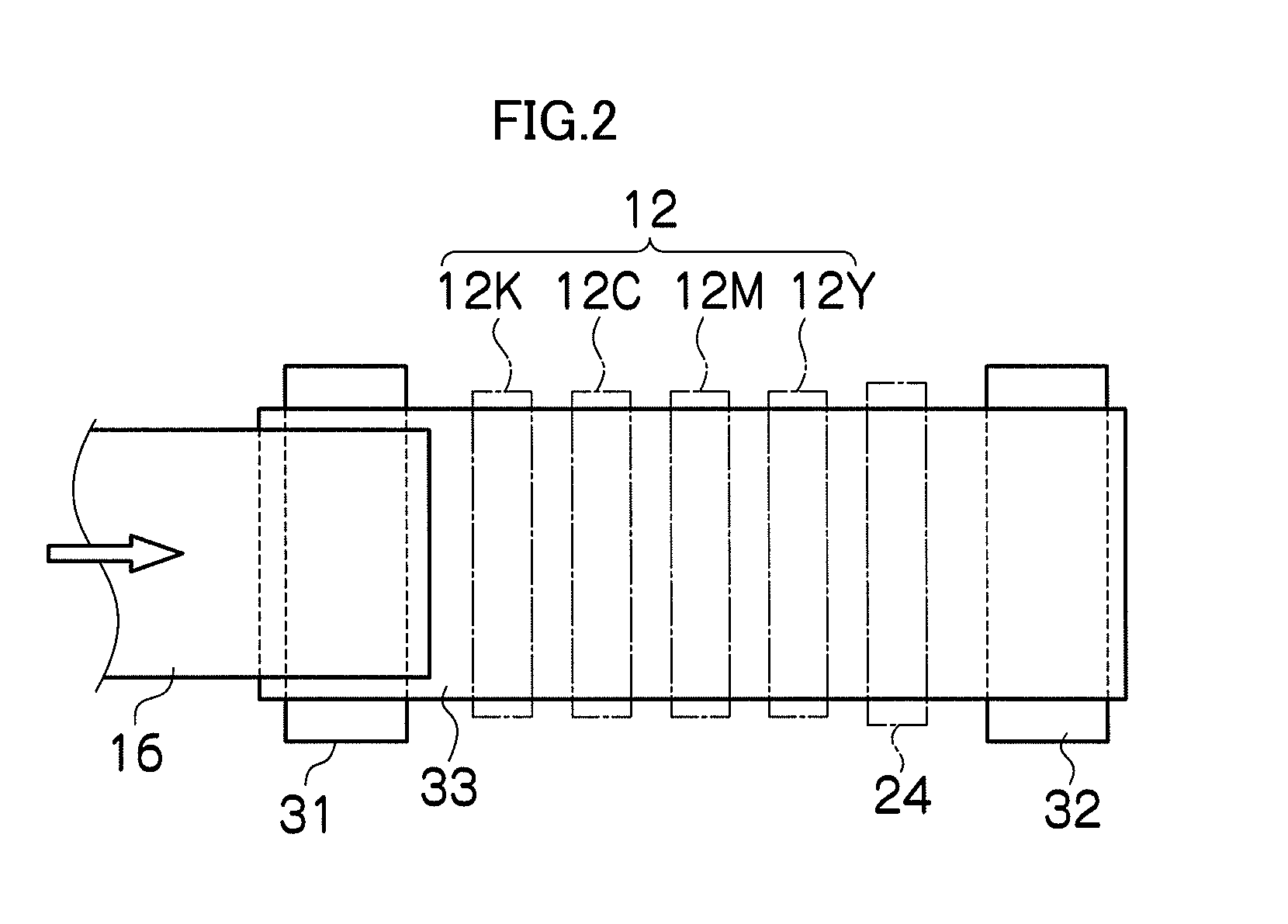
[0040]FIG. 1 is a diagram of the general composition of an inkjet recording apparatus according to an embodiment of the present invention. As shown in FIG. 1, the inkjet recording apparatus 10 includes: a print unit 12 having a plurality of inkjet heads (hereafter, called “heads”) 12K, 12C, 12M, and 12Y provided for colored inks of black (K), cyan (C), magenta (M), and yellow (Y), respectively; an ink storing and loading unit 14 for storing the inks of K, C, M and Y to be supplied to the heads 12K, 12C, 12M, and 12Y; a paper supply unit 18 for supplying recording paper 16, which is a recording medium; a decurling unit 20 removing curl in the recording paper 16; a suction belt conveyance unit 22 disposed facing the ink ejection faces (nozzle forming surfaces) of the heads 12K, 12C, 12M, and 12Y, for conveying the recording paper 16 while keeping the recording paper 16 flat; and a paper output unit 26 for outputting image-printed record...


PUM


Abstract

The liquid ejection head drive circuit includes: a drive voltage application device which applies drive voltage between a drive electrode and a common electrode of a piezoelectric element arranged in a liquid ejection head; a detection device which detects a current flowing in a common line which is electrically connected to the common electrode; an abnormal insulation determination device which determines a status of abnormal insulation of the piezoelectric element according to a detection result of the detection device; and a current limitation device which limits the current flowing in the common line within a prescribed range where the abnormal insulation determination device is enabled to determine the status of abnormal insulation, when the current flowing in the common line exceeds a reference value which is determined so that at least one of the detection device and the drive voltage application device is prevented from being overloaded.

Description

BACKGROUND OF THE INVENTION[0001]1. Field of the Invention[0002]The present invention relates to a liquid ejection head drive circuit, a liquid ejection apparatus, and a method of protecting such a liquid ejection head drive circuit, and more particularly to technology for protecting a drive circuit of a liquid ejection head including piezoelectric elements.[0003]2. Description of the Related Art[0004]Generally, an inkjet recording apparatus is broadly used as a general-purpose image formation device for forming color images. An inkjet recording apparatus includes, for example, inkjet heads corresponding to the respective colors of K (black), C (cyan), M (magenta), and Y (yellow), and is configured to eject color ink from the respective heads provided for the colors and forming the intended color image on a recording medium.[0005]In the inkjet head, ejection force generating elements such as piezoelectric actuators are provided respectively to a plurality of nozzles, and, when a pre...

Claims


Application Information

Patent Timeline
Patent Type & Authority Applications(United States)
IPC IPC(8): B41J2/045H01L41/09
CPCB41J2/0451B41J2/04541B41J2/0455B41J2/04555B41J2202/20B41J2/14233B41J2/155B41J2002/14459B41J2/04581
Inventor KATOH, YOSHINORI
Owner FUJIFILM CORP
Features
  • Generate Ideas
  • Intellectual Property
  • Life Sciences
  • Materials
  • Tech Scout
  • Unparalleled Data Quality
  • Higher Quality Content
  • 60% Fewer Hallucinations
Learn More