
Electronic apparatus

Inactive Publication Date: 2010-04-01
FUJITSU LTD
View PDF20 Cites 17 Cited by
  • Summary
  • Abstract
  • Description
  • Claims
  • Application Information

AI Technical Summary

Problems solved by technology

However, it is difficult for dust that has accumulated in the gap between the heat radiating fin and the cooling fan to be removed.
Further, when a dust collecting member is disposed between the heat radiating fin and the cooling fan, there is the fear that the dust collecting member will become a drag on the air blown from the cooling fan and lower the heat radiating efficiency of the heat radiating fin.
Further, there is the fear that the area of the heat radiating fin will become smaller and the heat radiating efficiency of the heat radiating fin will drop even more as a result of the dust collecting member being disposed.

Method used


Image

  • Electronic apparatus
  • Electronic apparatus
  • Electronic apparatus

Examples


Embodiment Construction

[0018]Reference may now be made in detail to embodiments of the present invention, examples of which are illustrated in the accompanying drawings, wherein like reference numerals refer to like elements throughout.

[0019]One embodiment of the present invention will be described below with reference to the drawings.

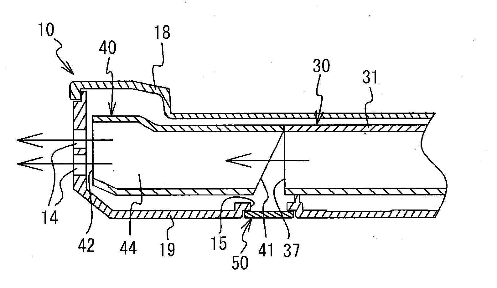
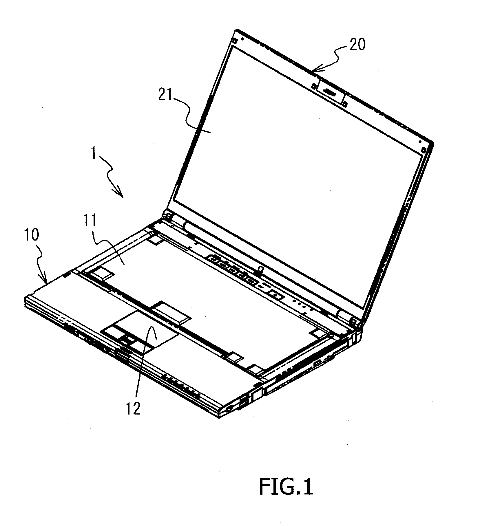
[0020]FIG. 1 is a perspective view of a notebook computer 1. The notebook computer 1 is one example of an electronic apparatus. The notebook computer 1 includes a body casing 10 and a display casing 20. FIG. 1 shows the notebook computer 1 in a state where the casings 10 and 20 have been opened. A keyboard 11 and a pointing device 12 are incorporated into the casing 10. A display 21 is incorporated into the casing 20. The casing 10 is one example of a casing that houses a heat radiating fin and a cooling fan described later.

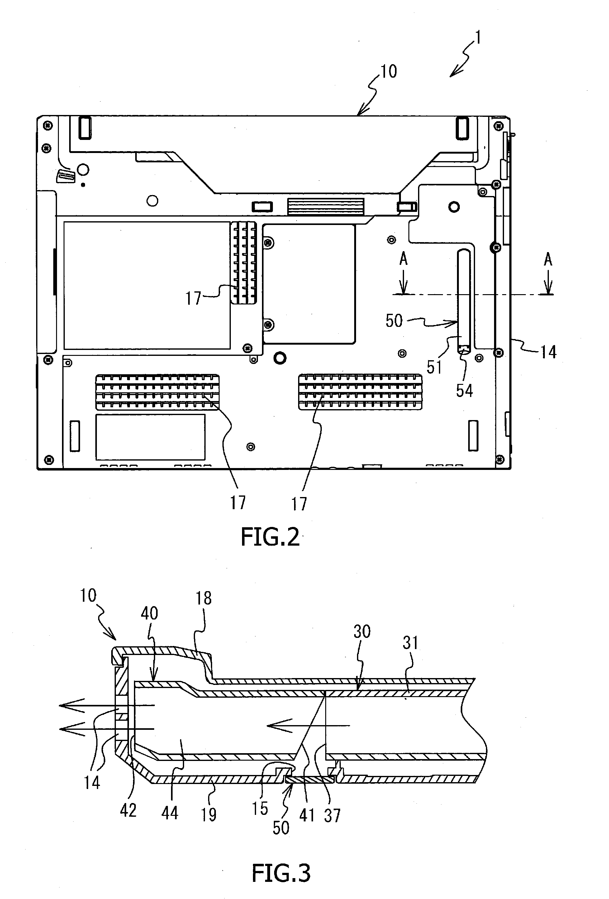
[0021]FIG. 2 is a bottom view of the casing 10. Air inlets 17 are disposed in plural places on the bottom side of the casing 10. Air is introduced to the...


PUM


Abstract

An electronic apparatus includes a casing that includes a vent, with the vent venting dust inside the casing, a heat radiating fin that is housed in the casing and includes an edge portion, a cooling fan that is housed in the casing and cools the heat radiating fin, with the cooling fan including an edge portion that faces the edge portion of the heat radiating fin. The electronic apparatus has a clearance between the edge portion of the heat radiating fin and the edge portion of the cooling fan becomes narrower the further it is from the vent.

Description

CROSS-REFERENCE TO RELATED APPLICATIONS[0001]This application is based upon and claims the benefit of priority from the prior Japanese Patent Application No. 2008-251437 filed on Sep. 29, 2008, the entire contents of which are incorporated herein by reference.BACKGROUND[0002]1. Field[0003]The embodiment described herein relates to an electronic apparatus that is equipped with a heat radiating fin and a cooling fan.[0004]2. Description of the Related Art[0005]There is known an electronic apparatus in which a heat radiating fin and a cooling fan that cools the heat radiating fin are housed inside a casing. Further, as disclosed in JP-A-2007-189183, for example, there is also known an electronic apparatus in which a dust collecting member for collecting dust is disposed between the heat radiating fin and the cooling fan, and an opening for replacing the dust collecting member is disposed in the casing.[0006]When the heat radiating fin and the cooling fan are disposed in proximity to ea...

Claims


Application Information

Patent Timeline
IPC IPC(8): H05K7/20
CPCG06F1/203
Inventor AOKI, SHINJI
Owner FUJITSU LTD
Learn More