
Communication device

a communication device and communication technology, applied in the field of communication devices, can solve the problems of affecting the transmission speed of packets, crowded ip networks, and significantly fluctuating packet transmission speed, and achieve the effect of smooth transmission and receiving of data

Inactive Publication Date: 2010-04-01
OKI DATA CORP
View PDF11 Cites 6 Cited by
  • Summary
  • Abstract
  • Description
  • Claims
  • Application Information

AI Technical Summary

Benefits of technology

[0015]In the present invention, the communication device includes the IP network determining unit for determining whether the destination device as a communication destination is connected through the IP network. When the IP network determining unit determines that the destination device is connected through the IP network, the communication control unit conducts the communication according to the second communication sequence more suitable for communicating through an IP network than the first communication sequence. Accordingly, it is possible to smoothly transmit and receive data between the communication device and the destination device.

Problems solved by technology

On the other hand, when the conventional communication device receives a training failure signal (a FTT signal) from the facsimile device indicating that the facsimile device fails to receive the TCF signal, the conventional communication device adjusts the transmission speed to a slower transmission speed by a specific decrement set in advance due to a modem training failure.
When a large number of devices connected to the IP network transmit and receive various signals and image data while sharing a plurality of routes, the IP network tends to be crowded.
In the IP network, when various signals and packets newly arriving queues exceed various signals and packets transmitting to the IP network from the queues, a conflict may occur due to delay in a packet transmission process for waiting for a queue or a large volume of packets, thereby significantly fluctuating the transmission speed of packets.
As a result, packets of the image data transmitted at the transmission speed thus adjusted become a queue waiting state, and are not transmitted within a specific period of time from a queue, thereby causing timeout.
When the timeout occurs, the conventional communication device is not able to transmit the image data to the facsimile device, thereby causing an error.

Method used


Image

  • Communication device
  • Communication device
  • Communication device

Examples


first embodiment

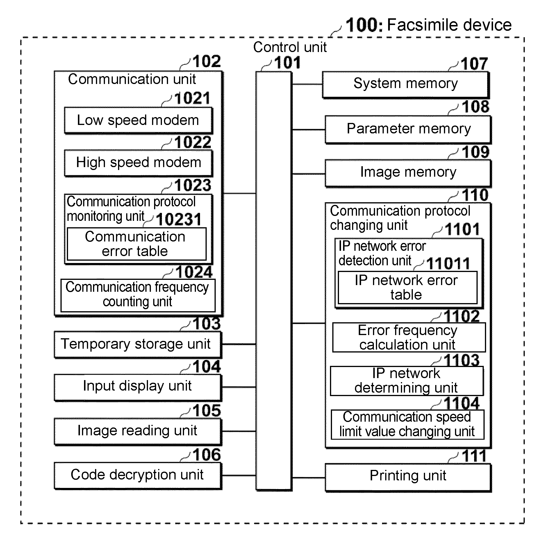
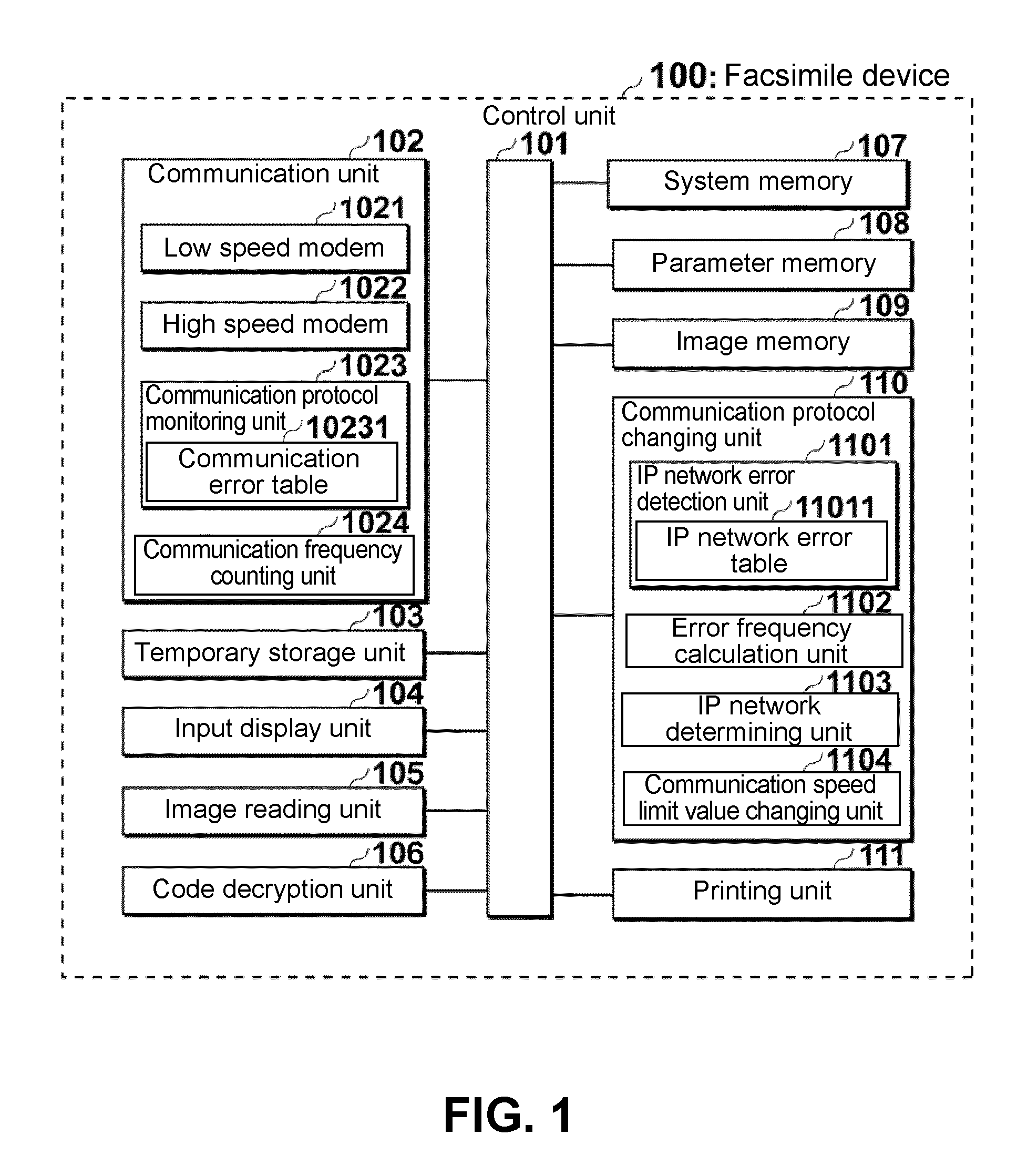
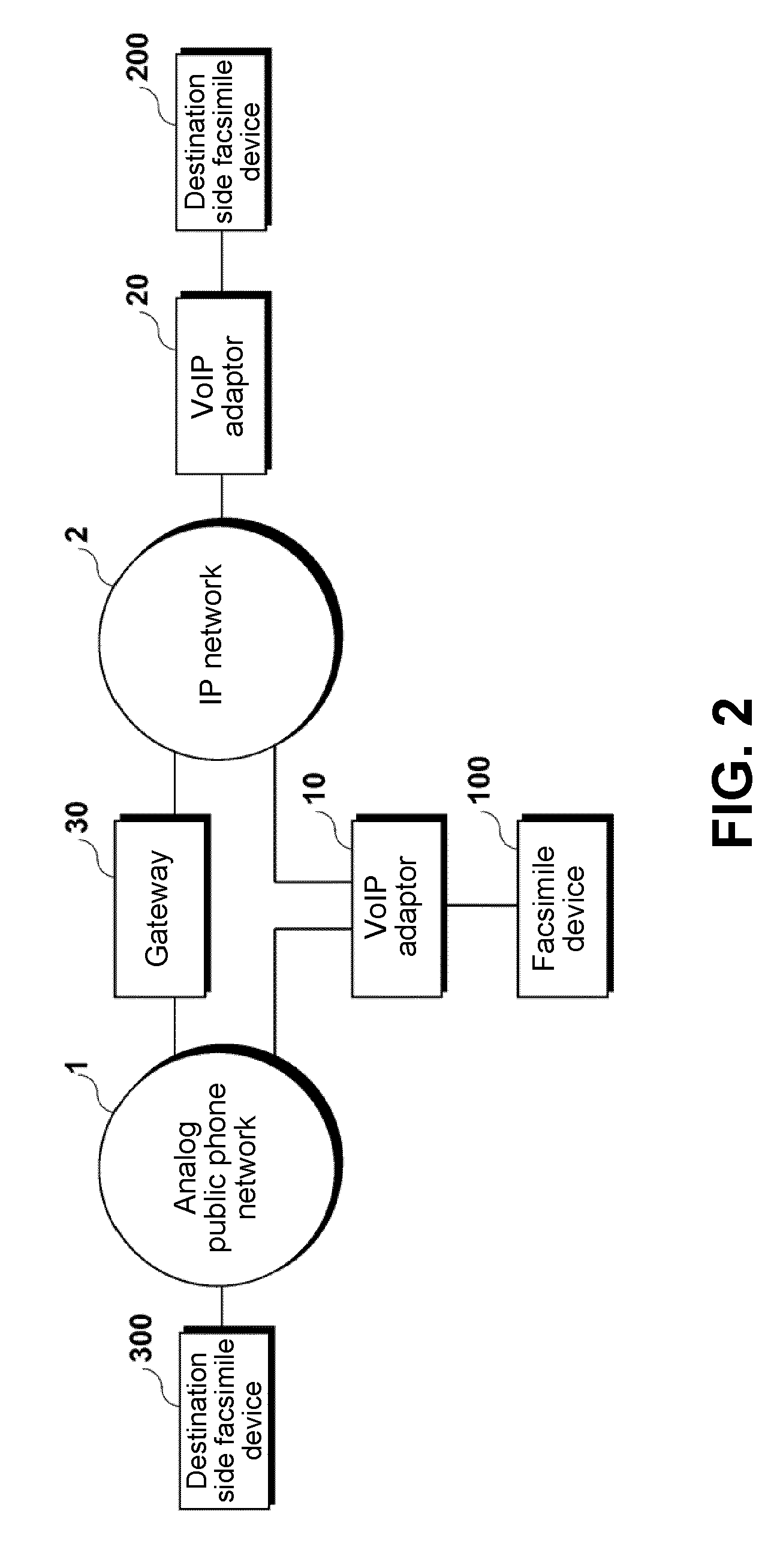
[0048]A first embodiment of the present invention will be explained. FIG. 1 is a schematic block diagram showing a configuration of a facsimile device 100 according to the first embodiment of the present invention. FIG. 2 is a schematic view showing a communication network according to the first embodiment of the present invention.

[0049]As shown in FIG. 2, the facsimile device 100 is connected to an analog public telephone network 1 and an IP network 2 through a VoIP adaptor 10. The analog public telephone network 1 is connected to the IP network 2 through a gateway 30. A destination side facsimile device 200 is connected to the IP network 2 through a VoIP adaptor 20. A destination side facsimile device 300 is connected to the analog public phone network 1.

[0050]In the embodiment, the VoIP adaptor 10 is connected to the IP network 2 when the facsimile device 100 conducts the facsimile communication with the destination side facsimile device 200, and is connected to the analog public...

second embodiment

[0176]A second embodiment of the present invention will be explained next. Components in the second embodiment similar to those in the first embodiment are designated with the same reference numerals, and explanations thereof are omitted. The components similar to those in the first embodiment provide similar effects, and explanations thereof are omitted.

[0177]FIG. 7 is a schematic block diagram showing a configuration of a facsimile device 100a according to the second embodiment of the present invention.

[0178]As shown in FIG. 7, the facsimile device 100a includes a communication unit 102a. The communication unit 102a includes an IP network connection tone digital information storage unit 1025; a connection tone detection unit 1026; a connection tone digital conversion unit 1027; and a connection tone digital information comparison determining unit 1028 (a determining unit).

[0179]When the facsimile device 100a as the transmission side facsimile device is connected to a facsimile dev...

third embodiment

[0205]A third embodiment of the present invention will be explained next. Components in the third embodiment similar to those in the first and second embodiments are designated with the same reference numerals, and explanations thereof are omitted. The components similar to those in the first and second embodiments provide similar effects, and explanations thereof are omitted.

[0206]FIG. 9 is a schematic block diagram showing a configuration of a facsimile device 100b according to the third embodiment of the present invention.

[0207]In the embodiment, when the facsimile device 100b is used as the transmission side facsimile device, it is arranged to register destination information in a destination area 1075 (a determining unit) of a system memory 107b through a button of the input display unit 104. The destination information indicates the fax number of the reception side facsimile device and whether the facsimile device 100b is connected to the reception side facsimile device throug...


PUM


Abstract

A communication device includes a communication control unit for conducting communication with a destination device according to a first communication sequence or a second communication sequence more suitable for communicating through an IP network than the first communication sequence. The communication device further includes an IP network determining unit for determining whether the communication is conducted through the IP network. When the IP network determining unit determines that the communication is conducted through the IP network, the communication control unit conducts the communication according to the second communication sequence.

Description

BACKGROUND OF THE INVENTION AND RELATED ART STATEMENT[0001]The present invention relates to a communication device having a facsimile function.[0002]As a conventional communication device, there has been proposed a facsimile device capable of communicating with another facsimile device connected thereto through an analog public telephone line (network) according to the ITU-T standard T.30 (refer to Patent Reference).[0003]Patent Reference: Japanese Patent Publication No. 2003-259098[0004]The conventional communication device starts communication through the following communication protocol. First, the conventional communication device sends a call signal (a CNG signal) to another facsimile device for sending image data to the facsimile device. After the conventional communication device sends the CNG signal, when the conventional communication device receives a digital identification signal (a DIS signal) from the facsimile device indicating a reception capability thereof, the conve...

Claims


Application Information

Patent Timeline
IPC IPC(8): H04L12/56H04N1/00H04N1/32
CPCH04M7/0069H04N1/00214H04N1/0022H04N2201/3335H04N1/33376H04N2201/002H04N2201/0027H04N1/33323
Inventor WATANABE, YUICHI
Owner OKI DATA CORP
Learn More