Eureka AIR delivers breakthrough ideas for toughest innovation challenges, trusted by R&D personnel around the world.

Evaporator

Inactive Publication Date: 2010-04-08
KEIHIN THERMAL TECH CORP
View PDF15 Cites 22 Cited by
  • Summary
  • Abstract
  • Description
  • Claims
  • Application Information

AI Technical Summary

Benefits of technology

[0007]An object of the present invention is to solve the above problem and to provide an evaporator which can prevent a sharp increase in the temperature of the discharged air, which sharp increase would otherwise occur when the compressor is turned off, and can prevent an increase in passage resistances within the header sections.

Problems solved by technology

Therefore, the effect of preventing a sharp increase in the temperature of the discharged air, which sharp increase would otherwise occur when the compressor is turned off, cannot be attained satisfactorily in some cases.
Therefore, passage resistances within the refrigerant inlet header section and the refrigerant outlet header section increase, so that performance may drop.
In particular, the increased passage resistance within the refrigerant outlet header section may result in a considerable drop in performance because the ratio of vapor-phase refrigerant present within the refrigerant outlet header section is high.

Method used


Image

  • Evaporator
  • Evaporator
  • Evaporator

Examples


Embodiment Construction

[0048]Embodiments of the present invention will next be described with reference to the drawings.

[0049]In the following description, the term “aluminum” encompasses aluminum alloys in addition to pure aluminum. Further, in the following description, the left-hand and right-hand sides of FIG. 1 will be referred to as “left” and “right,” respectively.

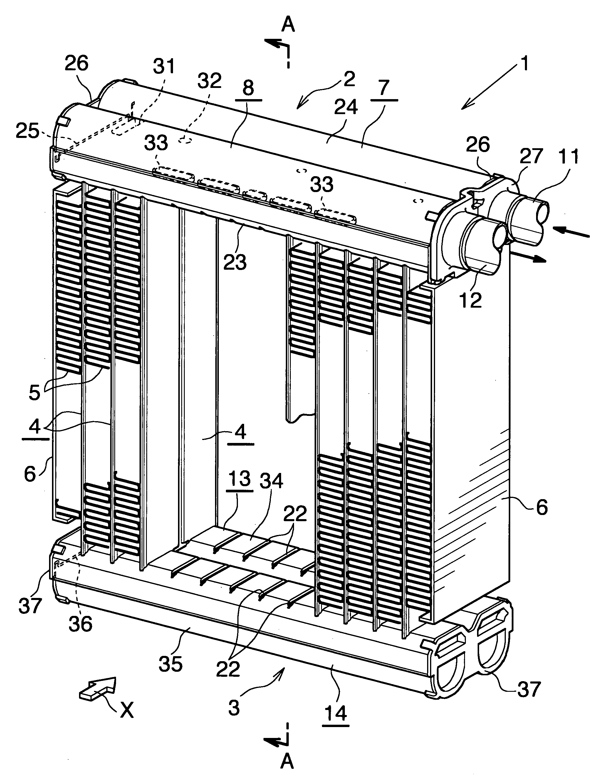
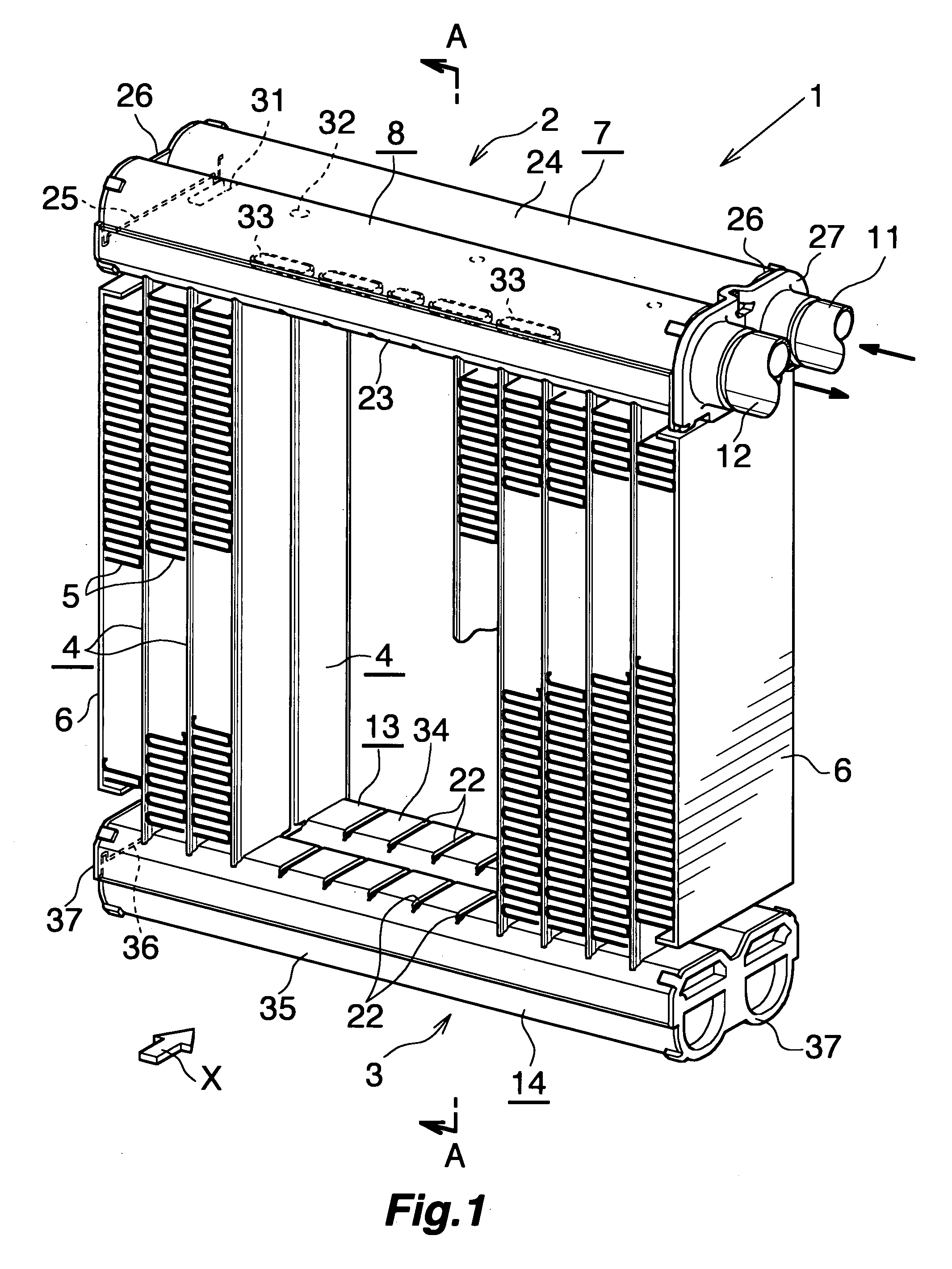
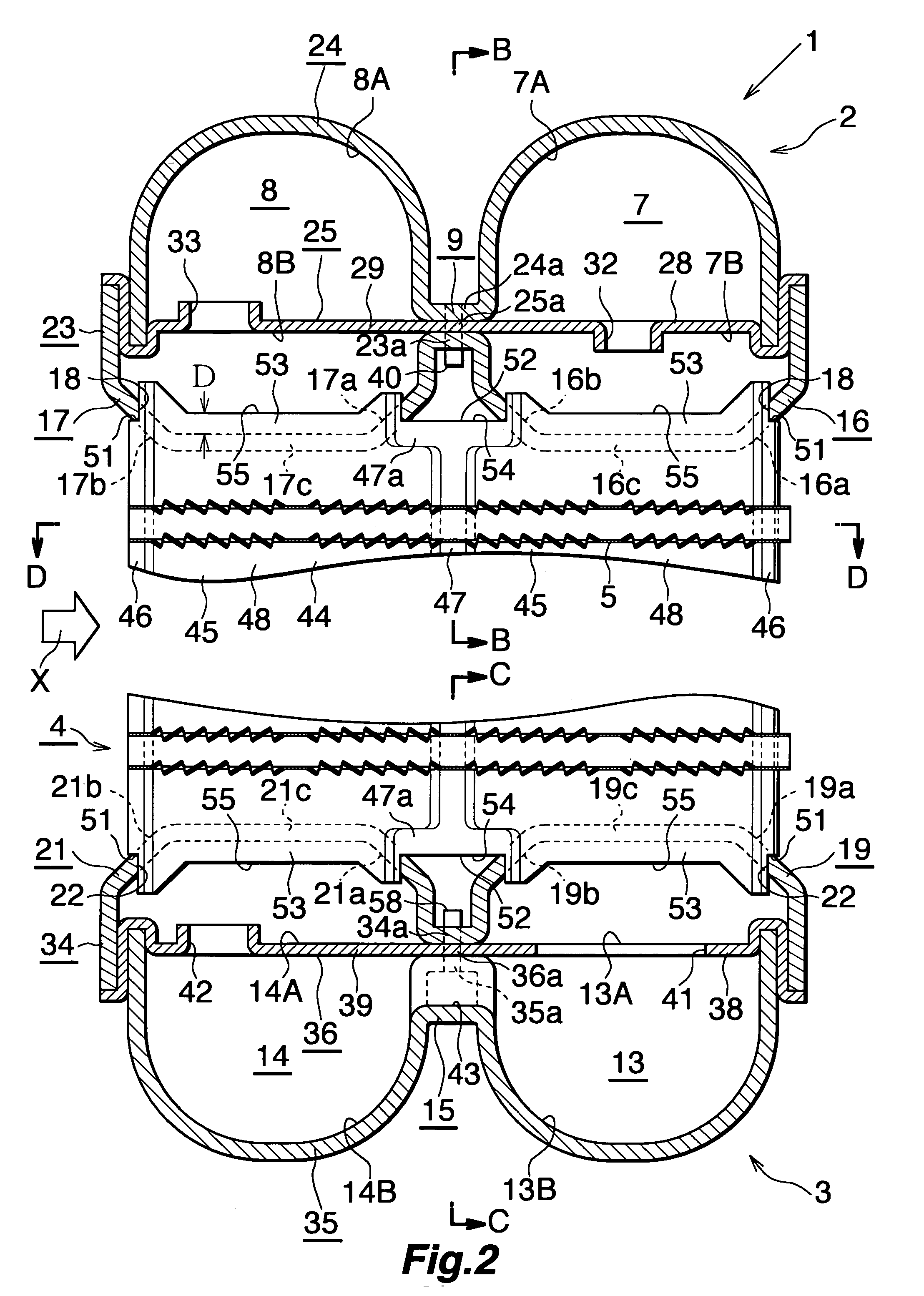
[0050]FIG. 1 shows the overall configuration of an evaporator, and FIGS. 2 to 9 show the configurations of essential portions of the evaporator.

[0051]As shown in FIGS. 1 and 2, an evaporator 1 includes a first header tank 2 and a second header tank 3 formed of aluminum and disposed apart from each other in the vertical direction such that they extend in the left-right direction; a plurality of flat heat exchange tubes 4 formed of aluminum and disposed between the two header tanks 2 and 3 such that their width direction coincides with the front-rear direction and they are spaced from one another in the left-right direction (the longitudina...


PUM


Abstract

Each heat exchange tube of an evaporator is composed of two press-worked rectangular metal plates joined together in a stacked condition. The metal plates of the heat exchange tube are swelled outward whereby at least one refrigerant flow space extending in the vertical direction and having opened upper and lower ends is provided in the heat exchange tube. Insertion portions to be inserted into header sections of header tanks of the evaporator via tube insertion holes are provided on upper and lower end portions of each heat exchange tube at positions corresponding to the refrigerant flow space. A concave portion is formed in each of the insertion portions, excluding opposite ends thereof with respect to the front-rear direction, of the upper and lower end portions of each heat exchange tube, the concave portion being concaved inward with respect to a longitudinal direction of the heat exchange tube.

Description

BACKGROUND OF THE INVENTION[0001]The present invention relates to an evaporator suitable for use in a car air conditioner, which is a refrigeration cycle to be mounted on an automobile, for example.[0002]In this specification and appended claims, the downstream side (a direction represented by arrow X in FIGS. 1, 2 and 10) of an air flow through air-passing clearances between adjacent heat exchange tubes will be referred to as the “front,” and the opposite side as the “rear.” Further, the upper and lower sides of FIGS. 1, 2, and 10 will be referred to as “upper” and “lower,” respectively.[0003]Recently, the present applicant has proposed an evaporator for a car air conditioner which satisfies the requirements for reduction in size and weight and higher performance (refer to Japanese Patent Application Laid-Open (kokai) No. 2008-20098). The evaporator includes a pair of header tanks disposed apart from each other in the vertical direction, and a plurality of flat heat exchange tubes ...

Claims


Application Information

Patent Timeline
IPC IPC(8): F25B39/02B60H1/32F28F9/00F28F1/10
CPCF25B39/022F28D1/05391F28D2021/0085F28F9/182F28F9/0224F28F9/0278F28F1/128
Inventor TAKAGI, MOTOYUKIHIGASHIYAMA, NAOHISAMINE, HOKUTO
Owner KEIHIN THERMAL TECH CORP
Why Eureka
Eureka Blog
Learn More