
Support Chain with Wear Protection for a Support Device for Separating Substances Having Different Flowabilities

a technology of support chain and flowability, which is applied in the direction of chain elements, solid separation, bone cleaning devices, etc., can solve the problems of high stress on the support chain, damage to the compression belt, and decrease in stability of the belt, so as to achieve high separation pressure

Inactive Publication Date: 2010-04-08
NORDISCHER MASCHINENBAU RUD BAADER GMBH CO KG
View PDF22 Cites 13 Cited by
  • Summary
  • Abstract
  • Description
  • Claims
  • Application Information

AI Technical Summary

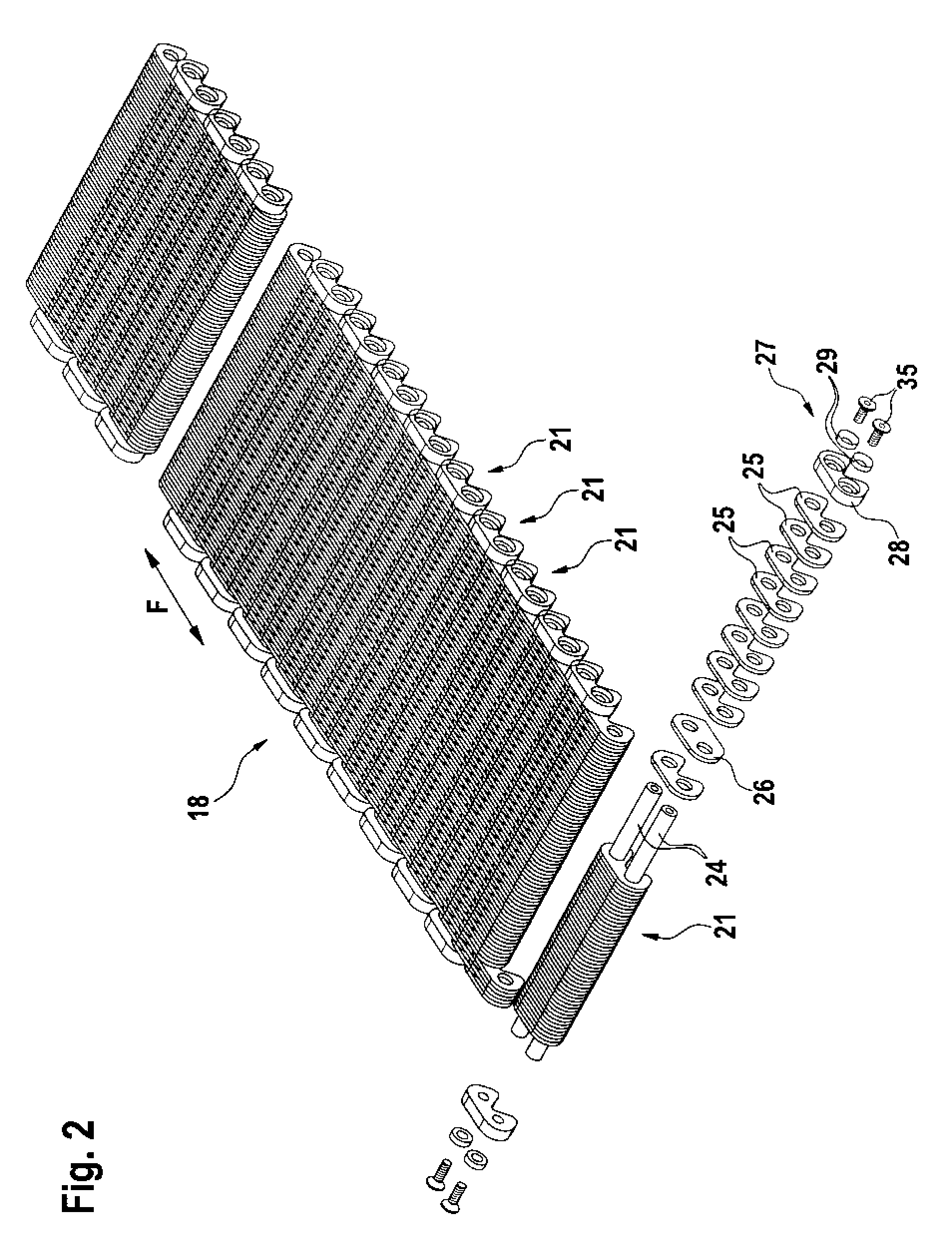
Benefits of technology

[0011]It is therefore an object of the present invention to provide a low-wear and resilient support chain capable of withstanding high separation pressures. It is further the object of the invention to propose a corresponding support device and a corresponding separation device.
[0012]This object is achieved by a support chain of the kind mentioned hereinbefore, by the fact that at the opposite free ends of the chain pins are arranged end pieces which are constructed and designed to receive the locking means in such a way that the support chain is planar on both sides facing transversely to the direction of conveying F of the support chain. This creates a flat sliding and / or friction surface which on the one hand assists guiding of the support chain between the side walls of the separation device and on the other hand reduces the wear on the support chain and / or side walls.
[0013]An appropriate development provides that each end piece connects two adjacent chain pins to each other and is composed of at least one sliding element and two compensating elements, the sliding element having recesses which are designed to completely receive the compensating elements and fastening means. This embodiment firstly ensures that the compensating elements and fastening means are completely countersunk within the sliding element, so that no obtrusive sections protrude beyond the flat outer surface of the sliding element. Secondly, the compensating elements prevent tilting / twisting of the chain links, which also causes an increase in the service life of the support chain.
[0014]Advantageously, the sliding element is hardened at least at the outwardly facing surface, which further increases the wear resistance.

Problems solved by technology

Due to these pockets of product, the compression belt is subjected to high stress as a result of local expansion, as a result of which its stability decreases greatly in time, as the compression belt wears out.
In general this results in damage to the compression belt, which in turn necessitates frequent changes of the compression belt.
Here, however, disadvantages arise, making it difficult to use this support device in practice.
Thus support belts likewise have a certain elasticity, on account of which the formation of pockets of product cannot be completely prevented when using support elements of this kind.
Furthermore, it is disadvantageous that the belts wear greatly due to the high mechanical load when pressed against the revolving compression belt, so that it is necessary from time to time to replace the worn belts with new belts.
This capacity for resistance on the one hand and eccentric delivery of the material to be compressed to the feeder nip on the other hand lead to the support chain slipping sideways.
As both the side walls, housing walls or the like and the support chain are made of steel, there is wear at certain points, which requires exchange of the support chain and / or the side walls, housing walls or the like.
This wear effect occurs particularly when using the previously used support chains, due to the fact that the chain pins are riveted or fixed by welding at their free ends in the region of a chain plate located on the outside.
As a result, considerable wear arises at the points of contact of steel on steel, which requires regular exchange of parts of the support chain or even the whole support chain.
Secondly, the compensating elements prevent tilting / twisting of the chain links, which also causes an increase in the service life of the support chain.

Method used


Image

  • Support Chain with Wear Protection for a Support Device for Separating Substances Having Different Flowabilities
  • Support Chain with Wear Protection for a Support Device for Separating Substances Having Different Flowabilities
  • Support Chain with Wear Protection for a Support Device for Separating Substances Having Different Flowabilities

Examples


Embodiment Construction

[0026]The support chain shown serves to support a compression belt in a separation device for separating substances having different flowability. Naturally, the support chain can also be used in other areas and for other purposes.

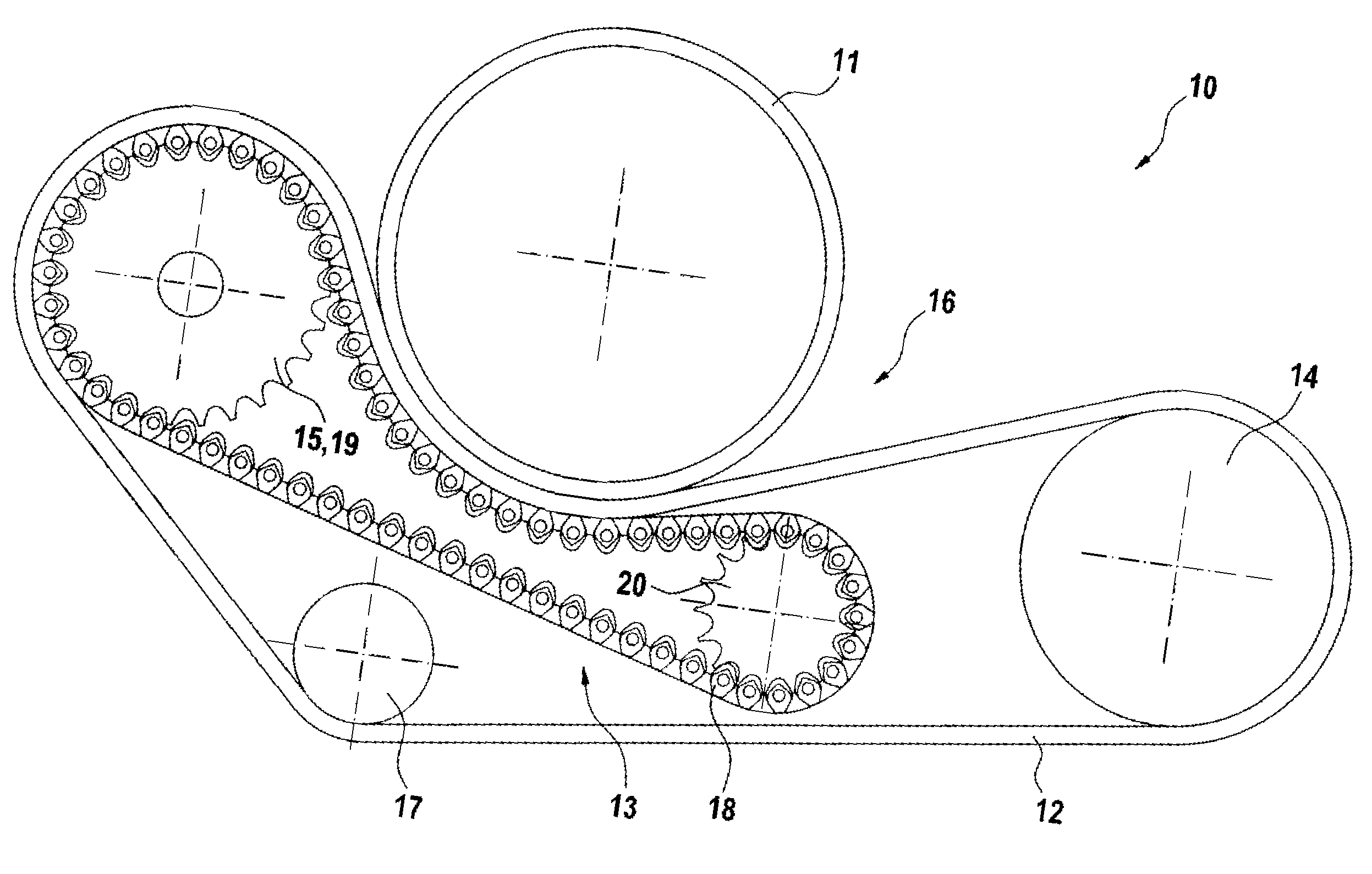
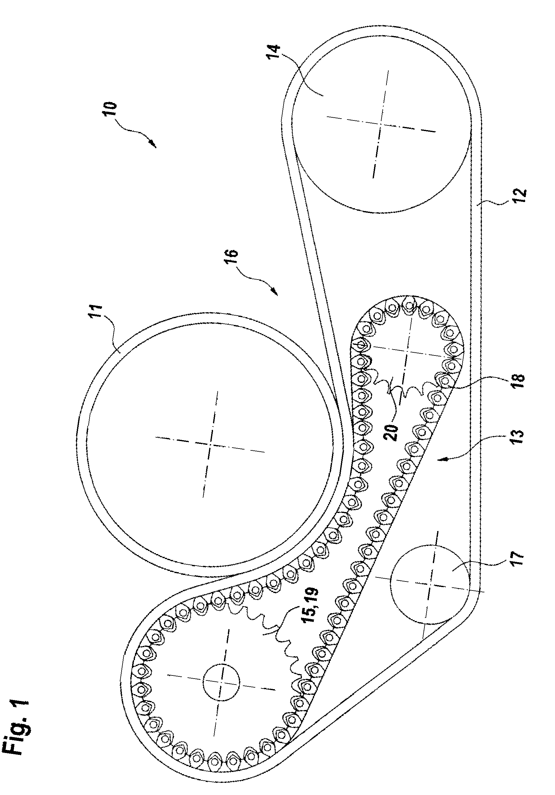
[0027]For a better understanding of the invention, first a separation device 10 is described with the aid of FIG. 1, in which the support chain according to the invention, which is described in detail below, is preferably used. The separation device 10 shown comprises a rotatably driven hollow drum 11 which has a shell with perforations. The hollow drum 11 mounted rotatably in a frame (not shown in FIG. 1; guiding side walls in FIG. 1 standing parallel to the plane of the drawing in FIG. 1 not shown (in FIG. 4 side walls 22, 23)) is wrapped over part of its circumference by an endless squeezing belt 12 (also termed compression belt in the following) which is made of an elastic material such as for example rubber, polyurethane or the like, either in the form...


PUM


Abstract

A support chain for a device for supporting a compression belt in a separation device for separating substances having different flowability. The support chain includes an articulated chain having individual chain links that form a flat surface. The links include chain pins with chain plates threaded thereon. A locking device is attached to opposite ends of the chain pins to hold the chain plates together on the chain pins. End pieces are adapted to receive the locking device so that the support chain is planar on both sides facing transversely to the direction of conveying of the support chain. Each end piece connects adjacent chain pins to each other and includes a sliding element and compensating elements. The sliding element has recesses which each include a through-bore and a non-through bore for receiving a respective compensating element. Each recess is constructed to receive the compensating element and locking device therein.

Description

CROSS-REFERENCE TO RELATED APPLICATION[0001]This application is a National Stage application of PCT / EP2008 / 002418 filed Mar. 15, 2008, which claims priority to German Application No. 20 2007 004 473.9 filed Apr. 7, 2008.BACKGROUND OF THE INVENTION[0002]The invention concerns a support chain for a support device for supporting a compression belt in a separation device for separating substances having different flowability, the support chain being an articulated steel chain and comprising individual chain links connected to each other and forming a substantially flat surface, wherein the chain links are composed of chain pins directed transversely to the direction of conveying F and have a plurality of chain plates threaded thereon, and the chain plates connecting two chain pins each together are held on the chain pins by locking means which are attached to opposite free ends of the chain pins.[0003]Furthermore, the invention concerns a support device for supporting a compression belt...

Claims


Application Information

Patent Timeline
IPC IPC(8): F16G13/04B07B13/00
CPCA22C17/04F16G13/08F16G13/04B30B9/241
Inventor HAHN, OLIVERGRANSEE, FRANKAVEY, RON
Owner NORDISCHER MASCHINENBAU RUD BAADER GMBH CO KG
Learn More