Printing Method for Printing Press and Printing Press

a printing press and printing press technology, applied in printing presses, printing press parts, printing, etc., can solve the problems of short service life of lamps, high cost, high cost, etc., and achieve the effect of reducing weight, reducing weight, and replacing quickly and easily

Inactive Publication Date: 2010-04-08
RYOBI
View PDF1 Cites 8 Cited by
  • Summary
  • Abstract
  • Description
  • Claims
  • Application Information

AI Technical Summary

Benefits of technology

The patent describes a printing method and press that use UV-cut glasses to shield areas of the sheet from UV light. This reduces the weight of the shielding part and the power needed to drive it. The method also allows for secure prevention of UV light exposure to areas other than the sheet, which improves service life, reduces heat generation, and power consumption. The press can track the total light time of the LEDs and replace them when the total light time reaches a predetermined level. These features make the printing method and press more efficient and easy to maintain.

Problems solved by technology

The technical problem addressed in this patent text is the corrosion and inaccuracy in registration caused by the use of ultraviolet curable inks on sheets of paper of a smaller width than the cylinder in printing presses that use ultraviolet lamps. Additionally, the use of light emitting diodes (LEDs) for curing the inks poses problems such as fluctuation in service life of each LED, difficulty in maintenance, and increased costs of the control device. The text proposes a solution to these problems by providing a printing press that uses a single ultraviolet lamp to cure the inks on sheets of paper of a smaller width than the cylinder, but this approach still poses problems of corrosion and inaccuracy in registration.

Method used


Image

  • Printing Method for Printing Press and Printing Press
  • Printing Method for Printing Press and Printing Press
  • Printing Method for Printing Press and Printing Press

Examples


Embodiment Construction

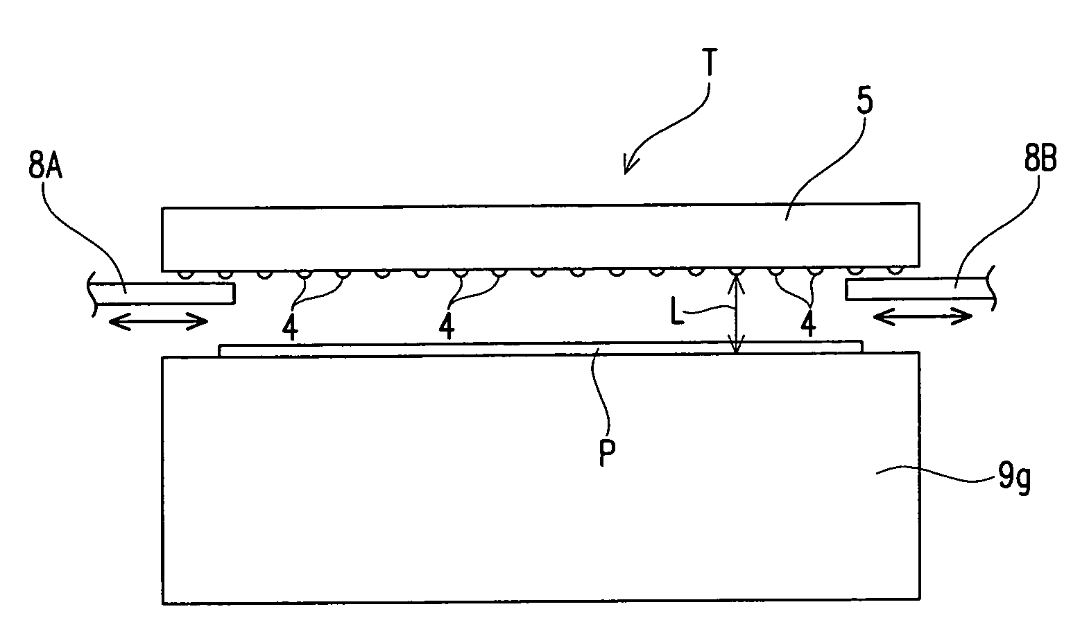
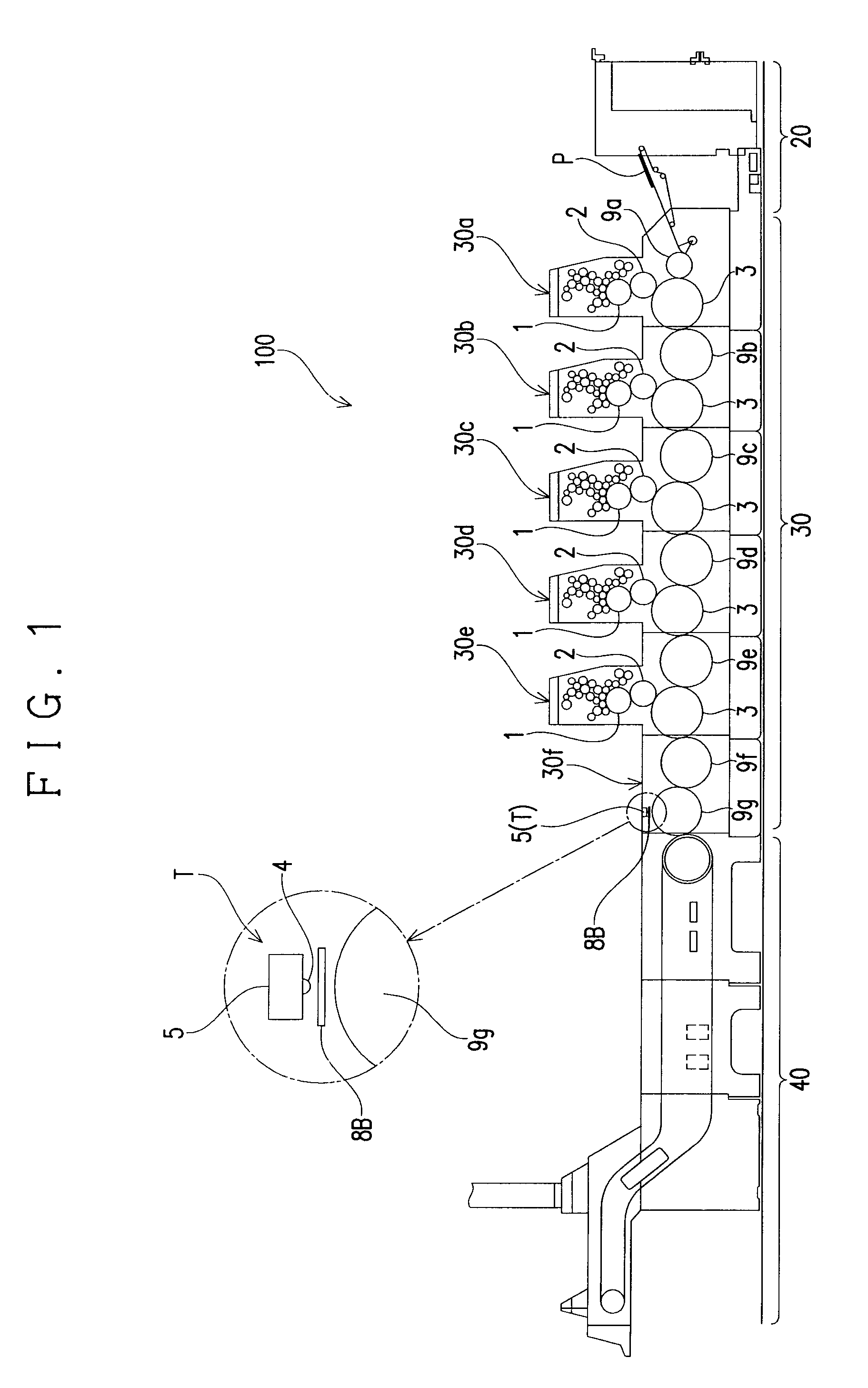
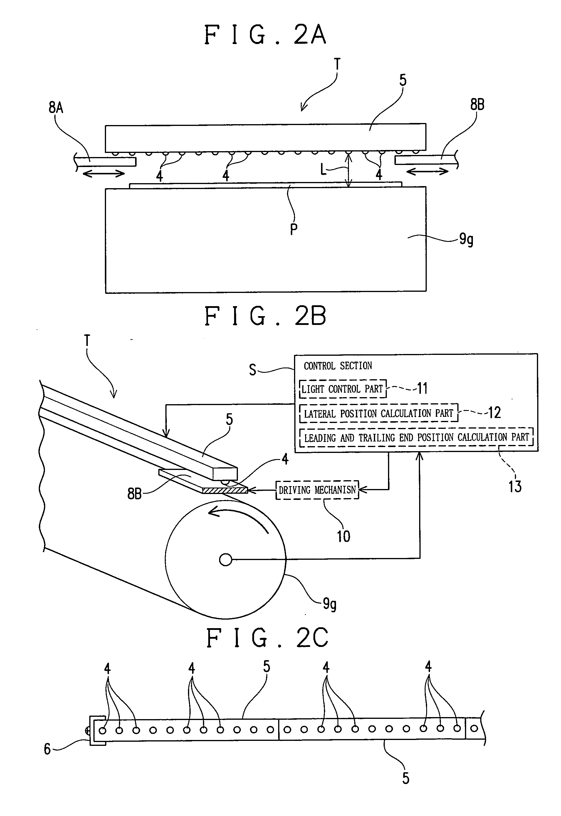
[0027]Embodiments of the present invention are described below with reference to the drawings. FIG. 1 shows an exemplary schematic configuration of a printing press 100 for implementing a printing method for a printing press according to the present invention. The printing press includes a control section S shown in FIG. 2 to be described later.

[0028]The printing press 100 is adapted to perform printing in five colors with inks of four basic colors that are different from one another, i.e., cyan (C), magenta (M), yellow (Y), and black (Bk), in addition to a special color, e.g., gold, silver, a fluorescent color, or a pearlized color for special color printing or complementary color printing. The printing press 100 includes a sheet feeder section 20, a printer section 30, and a sheet discharge section 40. The sheet feeder section 20 is capable of feeding sheets of paper P (hereinafter referred simply to as sheets P) into the printer section 30. The printer section 30 is capable of pe...


PUM


Abstract

An object is to provide a printing method for a printing press and a printing press that are capable of providing advantages in terms of service life, heat generation, and power consumption while overcoming various problems caused by ultraviolet irradiation. The method includes: printing an image on a sheet of paper fed using an ultraviolet curable paint; and irradiating the ultraviolet curable paint on the printed sheet fed by irradiating the ultraviolet curable paint with ultraviolet light from a plurality of light emitting diodes disposed at predetermined intervals across the transverse direction of the sheet, thereby curing the ultraviolet curable paint, wherein all the light emitting diodes are turned on while shielding a predetermined area in the transverse direction of the sheet from ultraviolet light.

Description


Claims


Application Information

Patent Timeline
Owner RYOBI
Why Eureka
Try Eureka